Certificate of visual inspection of welds. Ultrasonic testing (UT) Ultrasonic testing of the conclusion of the act protocol
Scanning
6.2.5.1 For scanning, thickness gauges or flaw detectors should be used that allow recording the relief of the controlled section in the range of product thicknesses from 1.5 to 30.0 mm at an ambient temperature from minus 10 °C to 40 °C. If it is necessary to work at temperatures below minus 10 °C, the measuring instruments and probes must be heated.
6.2.5.2 Scanning of the sheets of the first chord of the RVS wall (P, PC, PA) is carried out along the entire perimeter of the lower chord in a strip 300 mm wide from the morning seam; if ulcerative corrosion damage to the sheet is detected, an additional scan of this sheet is performed up to a height of 400 mm.
6.2.5.3 If there are repair pads on the inner surface of the wall, during the second stage of full technical diagnostics, the outer surface of the wall is scanned at the locations of these repair pads in order to identify corrosion damage and determine the minimum thickness.
6.2.5.4 Scanning results are presented in accordance with Appendix U.
6.2.6.1 Ultrasonic testing is used to control the quality of welded joints of tank structural elements. To carry out ultrasonic testing, general-purpose flaw detectors must be used, which in their technical characteristics comply with the requirements of GOST 23667, and/or specialized ultrasonic flaw detectors, including those equipped with semi-automatic and automatic scanning devices.
6.2.6.2 If there is a protective automatic transmission that meets the requirements
RD-23.020.00-KTN-184-10 and RD-77.060.00-KTN-221-09, an act is drawn up in accordance with
OR-23.020.00-KTN-278-09, appendix I and TTZ-23.020.00-KTN-117-10, appendices G and D, ultrasonic testing of metal and welded joints of walls and process pipelines located in the tank cage is carried out without removing coverings.
Note – When inspecting tanks (including all its elements, according to Table 6.1) with an automatic transmission under warranty, the coating is not removed, and the surface of the coating is cleaned of dirt and oil products in a manner that ensures the safety of the coating.
6.2.6.3 Ultrasonic flaw detectors must be equipped with a set of probes in accordance with the methodology, including technological (operational) ultrasonic testing cards developed for the equipment used (flaw detector and probe) and the connections being monitored.
Straight and inclined probes used with general-purpose flaw detectors must comply with the requirements of GOST 26266.
6.2.6.4 To check the technical characteristics and set up ultrasonic flaw detectors for general purposes, it is necessary to use:
Standard samples (СО-2 and СО-3), manufactured in accordance with GOST 14782;
SOPs made of the same material as the controlled object.
6.2.6.5 If specialized ultrasonic flaw detectors and/or semi-automatic and automatic scanning devices are used for ultrasonic testing, they are checked and adjusted in accordance with the operational documentation complete with the corresponding probes.
6.2.6.6 The flaw detectors must be adjusted at the control temperature. Ultrasonic testing is carried out in accordance with a methodology that includes technological (operational) ultrasonic testing cards developed for the equipment used (flaw detector and probe) and the connections being monitored.
6.2.6.7 Ultrasonic testing is carried out in automatic mode with data recording in the memory of the ultrasonic flaw detector and subsequent saving of files in the PC memory. In places where automatic control is not possible, manual control is allowed.
6.2.6.8 The ultrasonic testing methodology and equipment used must ensure the detection of defects in accordance with SNiP 3.03.01-87 and RD-19.100.00-KTN-001-10 in welds subject to inspection (including in places where seams cross) and pipelines.
6.2.6.9 For defects detected during ultrasonic testing, the following characteristics are determined:
Echo signal amplitude;
Conditional length of the defect;
Maximum depth of the defect;
Height of the defect.
6.2.6.10 When assessing the results of ultrasonic testing, the screening of defects and welded joints is carried out according to the amplitude of the received signals, the conditional length of defects, the total conditional length of defects and the number of defects detected in the evaluation area.
6.2.6.11 The dimensions of the cross sections of the wall welds on which ultrasonic testing is performed during partial technical diagnostics are shown in Figure 6.12.
Figure 6.12 – Dimensions of controlled sections of weld crosshairs
6.2.6.12 Ultrasonic inspection of welded seams of the dome roof support ring segments is carried out in accessible places after opening the cards; during subsequent diagnostics, ultrasonic inspection of uninspected welds is carried out.
6.2.6.13 The results of the ultrasonic testing are documented in an act in accordance with Appendix F and
RD-19.100.00-KTN-299-09. When drawing up a conclusion, each defect should be described separately. The ultrasonic inspection report is accompanied by inspection diagrams, conclusions based on the ultrasonic inspection results, and sketches of the tank structures indicating the coordinates of the location of the identified defects.
Control of welds is a necessary part of the approval of various structures before operation. The methods and results of verification actions are reflected in a special act.
FILES
How to check welds
In fact, a variety of methods can be used to examine welds, for example, ultrasonic, magnetic, chemical, capillary and other high-tech methods. However, the classic one, which is still relevant and in demand today, is a simple visual inspection. Its purpose: to make sure that the seam is of high quality, well welded, and has no undercuts, sagging, burns, excessive scaliness or other flaws. The advantages of this type of research are quite obvious: it does not require large expenses, it is accessible and quite informative, but along with this there are also disadvantages: the subjectivity of the examination, low reliability, the ability to examine only the visible part of the seam.
Visual inspection can be carried out both with the naked eye (usually, if we are talking about large, clearly visible seams), and with the help of various devices, such as lenses, microscopes, endoscopes, flaw detectors, etc.
They are used to identify the smallest hidden defects that are difficult to detect by simply examining the outside of the weld (for example, microscopic cracks, nicks, delamination, fractures, etc.). At the same time, there are devices that are intended only for use in laboratories and those that can be used “in the field.” The latter are able to withstand any temperature and weather conditions (including those that have an increased coefficient of radiation, chemical, bacteriological, etc. danger to humans).
Why is weld inspection necessary?
The purpose of such an in-depth examination is quite obvious: as a rule, any structures that use welding are designed to withstand a certain, quite serious load (this is especially true for building structures). And any deviation from technical standards that occurs during their manufacture threatens that the structure will not withstand and will break, which in turn can lead not only to financial losses, but also to a threat to the life and health of people.
Often, welds are checked not only after the structure is manufactured, but also during its operation - this is due to the fact that they may be subject to corrosion and other adverse effects. Also, regular checks are necessary when surfacing several layers on a worn-out structure, while each completed layer is monitored, the length of the weld, the thickness of the base metal are measured, and these data are compared with the established standard for this area, taking into account its load.
The frequency of inspections is determined by legal norms, as well as internal regulations of the company.
Timely and high-quality visual inspections make it possible to detect seam failure as early as possible, as well as understand the causes and find a way to eliminate them.
Who carries out the inspection and draws up the report
The initial quality check of the weld is done by the welder who performed it. Further control is carried out by other employees: for example, the site manager, engineer, etc. It is important that these persons have the necessary knowledge of the technique of visual inspection of welds, and are also equipped with the necessary instruments and devices. They should also have an idea of how to formulate a visual inspection report for welds.
Act format
Today there is no uniform standard for the act, which means that it can be done in any form. However, if the organization has its own document template, which is developed and approved by management, then it should be used. It is good if the format of the act is specified in the accounting policy of the enterprise.
Features of drawing up a visual inspection report for welds
There are also no requirements regarding the execution of the act, that is, it can be written by hand or typed on a computer; a form with a company logo and details and an ordinary piece of paper are suitable for it. The only thing: if an electronic form was made, then it should be printed so that the signatures of the responsible persons can be placed on it. The act is made in one original copy, which must be assigned a number.
Registration and storage of the act
Information about the act must be entered in a special accounting journal, in which it is enough to make a note about its number and date of creation. The storage period for the finished act is determined by the administration of the enterprise individually, based on the norms established by law, as well as the internal needs of the company.
The act must be stored in a separate folder either in the structural unit in which it was generated, or in the archive of the organization.
If you need to draw up a weld inspection report that you have never done before, use the sample below and read the comments to it - they will help you draw up the required document without errors and ambiguities.
- First of all, enter the name of the enterprise into the act, then assign a number to the document, indicate the date and place of its creation.
- Next, enter into the report the positions and full names of the workers who inspected the weld (if these are representatives of different enterprises, indicate the names of each of them).
- After this, proceed to the main part: include information about the performer of the work: position, full name, then enter here data about the welds that were examined: their number, steel grade and other identification values.
- Indicate the instruments and devices that were used during the inspection, all the methods used, their results, and also give recommendations on additional examination methods.
- At the end, be sure to summarize the current control and sign.
MANAGEMENT
BY ULTRASONIC
CONTROL
QUALITIES
WELDED BUTT AND
T-JOINTS
FITTINGS AND EMBODIED PARTS
REINFORCED CONCRETE STRUCTURES
Moscow 1981
The section of reinforced concrete structures of the NTS NIIZhB of the USSR State Construction Committee dated July 21, 1981 is being printed.
The manual contains rules and methods for non-destructive ultrasonic quality control of welded joints of reinforcing bars of reinforced concrete structures made by butt welding and multilayer welding methods in inventory forms and on steel remaining brackets or linings, as well as T-shaped embedded parts welded under submerged arcs.
The manual is intended for engineering and technical workers of quality control services.
Table 8, ill. 12.
PREFACE
This Guide has been compiled as a development of GOST 23858-79 “Welded butt and T-joints of reinforced concrete structures. Ultrasonic quality control methods. Acceptance rules."
The manual contains the basic provisions for ultrasonic quality control of butt joints of reinforcing bars of reinforced concrete structures, made by bathtub and multilayer methods, welded in inventory forms and on steel remaining brackets-plates or linings, as well as T-shaped embedded parts welded under submerged arcs.
Ultrasonic testing allows you to identify welding defects, cracks, lack of fusion, pores and slag inclusions. The control method is highly reliable, efficient, highly productive, cheap, safe, allows for 100% control if necessary, and helps to increase the reliability and durability of prefabricated and monolithic reinforced concrete structures.
The manual was developed by the Research Institute of Concrete Construction of the USSR State Construction Committee (Candidate of Technical Sciences A.M. Fridman), KTB Research Institute of Concrete Concrete Construction of the USSR State Construction Committee (eng. G.G. Gurov) and the Moscow Higher Technical School named after. N.E. Bauman of the USSR Ministry of Higher Education (candidate of technical sciences N.P. Aleshin, engineers A.K. Voshchanov, E.M. Komov).
Please send comments and suggestions regarding the content of this Manual to NIIZhB at the address: 109389, Moscow, 2nd Institutskaya St., 6.
|
Directorate of NIIZhB |
GENERAL PROVISIONS
1.1. This Guide applies to ultrasonic testing of butt connections of reinforcement with each other and T-joints of reinforcement with flat rolled steel elements, performed during the manufacture of embedded parts, installation of prefabricated and construction of monolithic reinforced concrete structures for any purpose; establishes methods for ultrasonic quality control of welded seams to identify cracks, lack of fusion, pores and shock inclusions.
1.2. Ultrasonic testing methods given in this Manual should be used for quality control:
a) butt single-row connections of reinforcement bars with a diameter of 20 to 40 mm made of steel classes A-I, A- II and A-III according to GOST 5781-75, made by bathtub and multilayer welding methods in inventory forms and on steel remaining brackets or linings, as well as without forming and auxiliary elements;
b) butt single-row connections of reinforcement bars with a diameter of 45 to 80 mm made of class A-II steel according to GOST 5781-75, made on steel remaining brackets or linings;
c) T-joints of reinforcement bars with a diameter of 8 to 40 mm with flat rolled steel elements with a thickness of 6 to 30 mm, made by submerged arc welding.
1.3. Welded butt joints of rods with a diameter ratio of 0.8 - 1.0 are subject to ultrasonic testing.
1.4. The ultrasonic testing methods presented in this Manual are intended to identify internal defects without deciphering their nature and accurately determining their coordinates in welded joints.
A characteristic of the quality of the connection is the amplitude of the ultrasonic signal transmitted through the weld or reflected, measured in decibels.
Note. Quality control methods allow us to approximately determine the location of the defect (edge or central), which is necessary for welding services to take measures to eliminate the causes of defect formation (see paragraph of this Manual).
1.5. Quality control of welded joints of reinforcement is carried out using the following methods:
a) shadow - butt joints of rods made in inventory forms or without forming auxiliary elements (Fig. , a);
Rice. 1. Schemes of ultrasonic testing methods:
a - shadow; b - mirror-shadow; c - echo-pulse;
1 - inclined transducers; 2 - separate-combined (PC) converters; 3 - mark corresponding to the beam exit point; 4 - welded connection; 5 - bracket-plate; 6 - rod; 7 - embedded part plate (G - output to the ultrasonic vibration generator; P - output to the receiver)
b) mirror-shadow - butt joints of rods made on steel brackets or pads (Fig. , b);
c) echo-pulse - T-joints of rods of embedded parts made under submerged arc (Fig. , c).
Note. Flank seams in connections made on steel brackets (for example, bath-seam welding) are not subject to ultrasonic testing. They are accepted by visual inspection in accordance with GOST 10922-75 in the same way as extended seams of welded joints.
1.6. Ultrasonic testing of welded joints of reinforcement of reinforced concrete structures should be carried out by operators who have undergone special training according to the program developed by NIIZHB and MVTU, and who have the appropriate certificate.
1.7. The qualifications of a flaw detector operator are checked, regardless of his work experience, at least once every 6 months, as well as in the event of a break in work for more than 3 months.
1.8. The composition of the qualification commission is approved by order of the head of the organization (enterprise). The commission may include highly qualified specialists from other organizations.
1.9. Qualification tests are carried out by the commission or in the presence of a representative designated by it.
1.10. For qualification tests, 6 control samples (6 welded joints) are selected, subjected to ultrasonic testing in accordance with GOST 23858-79 with mandatory subsequent mechanical tests in accordance with GOST 10922-75, and the results obtained are compared.
1.11. In case of unsatisfactory results (2 or more errors were made), repeated tests are allowed on a double number of samples. If unsatisfactory results are obtained during repeated tests, the flaw detector operator may be re-admitted to testing no earlier than after 1 month. after additional preparation.
1.12. If there are a large number of defects or their absence, or other situation that casts doubt on the correctness of the control, the chairman of the qualification commission or a representative of the controlling organization may assign (or require) an extraordinary inspection of the work of the operator, equipment, etc.
1.13. All qualification tests carried out must be recorded with appropriate documentation, on the basis of which a document is issued for the right to carry out work on ultrasonic flaw detection.
1.14. Before ultrasonic testing, welded joints are subjected to visual inspection for measurement in accordance with the requirements of GOST 10922-75. Rejected welded joints are not subject to ultrasonic testing until the detected defects are corrected.
1.15. The surface of the rods and plates at the points of contact with the transducers must be cleaned to bare metal from hardened concrete, metal splashes, slag residues, burrs, flaking scale, rust and other contaminants. Cleaning should be done with a hammer-chisel and a wire brush.
1.16. Ultrasonic testing of welded butt joints of rods can be performed at ambient temperatures from +40 to -25 °C.
1.17. Ultrasonic testing of T-joints of embedded parts rods can be performed at ambient temperatures from +40 to +5 °C.
2. EQUIPMENT AND MEANS OF ULTRASONIC CONTROL
2.1. To control welded joints the following should be used:
pulsed ultrasonic flaw detector;
set of transducers: a) inclined - for monitoring butt joints of rods; b) separate-combined (PC) - for monitoring embedded parts;
mechanical devices for monitoring butt joints of rods and templates-devices for monitoring embedded parts;
sets of standard samples according to GOST 14782 -76;
test samples of butt joints of rods;
test samples for embedded parts.
2.2. A pulsed ultrasonic flaw detector must operate according to a separate testing circuit and have a calibrated attenuator with a division value of no more than 2 dB, for example, flaw detectors DUK-66PM or type UZD-MVTU-1T powered from an external network or batteries.
2.3. When monitoring connections, the flaw detector-transducer system must provide on the test sample or on the plate of the embedded part the value of the reference signal (in dB) not lower than the values given in table. .
Table 1
|
Amplitude of reference signals, dB |
|||||
|
Diameter of rods, mm |
|||||
|
8 10 12 14 16 18 |
20 22 25 |
28 32 |
36 40 |
50 60 70 80 |
|
|
Butt in inventory form and on a steel bracket-plate or lining |
|||||
|
Tavrovoe |
|||||
Note. The reference signal is the signal obtained during the passage of an ultrasonic wave from the emitting to the receiving transducer in the absence of defects along this path in the test sample when testing butt joints of rods or on a flat element when testing embedded parts.
2.4. To control butt joints of rods and T-shaped embedded parts, inclined (Fig.) and PC transducers (Fig.) should be used. The parameters of the converters and their testing must correspond to those given in table. of this Manual, GOST 23858-79 and GOST 14782-76, as well as in regulatory documents for the manufacture of converters.
Rice. 2. Slope transducer design
1 - high-frequency cable; 2 - damper; 3 - piezoelectric element; 4 - prism ( b - prism angle; 2 a - diameter of the piezoelectric element; P- converter boom)
Rice. 3. Design of the PC converter
1 - reception; 2 - piezoelectric element; 3 - damper; 4 - connecting conductors; 5 - body; 6 - screen (h- delay length; b - prism angle; 2 A- side of the square of the piezoelectric element)
2.5. The contact surface of inclined transducers must have a radius of curvature determined by the diameter of the periodic profile rod in accordance with GOST 5781-75. The required radius of curvature is obtained by milling the transducer prism during its manufacture or by grinding in the finished transducer by moving it longitudinally along a rod wrapped in sandpaper. Inclined and PC converters must have a surface finish of at least P z 200 µm according to GOST 2789-73; wear on the surface of the transducers is measured using a template or probe (type KL-2 No. 5 MB).
Note. Converters having a radius of curvature determined by the diameterd 1 , can be used to control butt joints with rod diametersd n 2 - 3 numbers below ground-in.
table 2
|
Converter type |
Rod diameters, mm |
Converter parameters |
||
|
frequency, MHz |
prism angle, degrees |
|||
|
Butt in inventory form |
Inclined |
20 - 40 |
||
|
Butt on a steel bracket-plate or lining |
20 - 32 |
50 * |
||
|
36 - 40 |
50 * |
|||
|
45 - 80 |
||||
|
Tavrovoe |
8 - 22 |
|||
|
25 - 40 |
||||
______________
* To control butt joints of rods with a diameter of 20 - 40 mm, made on steel brackets, it is allowed to use transducers with a prism angle b = 45°.
2.6. When monitoring rod connections, transducers should be installed in mechanical devices (Fig. ), which should provide:
constant distance between transducers when testing rods of a certain diameter;
changing the distance between the transducers when switching to monitoring connections of rods of a different diameter;
installing the transducers on a controlled connection coaxially relative to each other and the rods;
constant, independent of the operator, pressing force of the transducers to the rods;
possibility of moving transducers along the rod.
2.7. When inspecting welded joints of embedded parts, a mechanical template-device is used to limit the scanning area with the transducer along the plate above the welding site of the rod (Fig.). The scanning area is limited using a replaceable limit ring.
Rice. 4. Diagrams of mechanical devices for ultrasonic testing of butt joints of rods made by bath welding in the inventory form (a) and bath seam welding on the remaining bracket-plate or lining (b)
1 - strip for mounting converters; 2 - levers; 3 - handle; 4 - clamp; 5 - frame; 6 - converter; 7 - clamping device
Rice. 5. Diagram of a template-device for ultrasonic testing of T-joints of rods with a flat rolled element, made by submerged arc welding
1 - latch; 2 - restrictive ring; 3 - levers
Note. The longitudinal ribs of the periodic profile of the butting rods of the test sample should be positioned at an angle of 90 ± 5° relative to each other.
In exceptional cases, it is allowed to use the base metal of the reinforcing bar as a test sample.
2.9. To make a set of test samples, four joints should be welded in accordance with the instructions of paragraph of this Manual, then radiographic examination should be carried out, the two best samples should be set aside, and the remaining two should be subjected to mechanical tests in accordance with GOST 10922-75. If it is impossible to carry out transillumination, it is necessary to make six control samples, check them with ultrasonic flaw detection, select the two best ones, and subject the remaining four to mechanical tests in accordance with GOST 10922-75. If the results of mechanical tests of samples do not satisfy the requirements of GOST 10922-75, a batch of test samples should be made again, repeating the above operations.
Rice. 6. Diagram of a test sample for adjusting the sensitivity of a flaw detector when inspecting butt joints of reinforcing bars made in inventory form (a) and on a bracket-plate or lining (b)
1 - converter; 2 - welded connection; 3 - bracket-plate or lining
|
d n rod |
|||||||||||||
|
d holes |
Rice. 7. Diagram of a test sample for monitoring T-joints of embedded parts made by automatic welding
d - plate thickness (corresponds to the thickness of the plate of the controlled part); D - height of the rim
3. METHOD OF ULTRASONIC INSPECTION OF WELDED BUTT JOINTS OF REINFORCING RODS
3.1. Ultrasonic testing of butt joints of rods is carried out according to the shadow scheme (see Fig., a) for connections made in inventory forms or without forming auxiliary elements, and according to the mirror-shadow scheme (see Fig., b) - for connections made on steel brackets or pads. Reducing the signal amplitude A max passed through a defective weld joint, compared to the amplitude of the reference signal A 0 obtained on the test sample indicates the presence of a defect. Relative amount of signal attenuation D A = A 0 - A max is proportional to the size of the defect in the welded joint.
Distance between transducersl, mm
rod diameter, mm
45 - 50
Butt in inventory form (horizontal)
Butt in inventory form (vertical)
Butt on a steel bracket-plate or lining (horizontal or vertical)
160 *
192 *
224 *
256 *
64 *
70 *
80 *
90 *
102 *
115 *
128 *
______________
* For transducers with prism angle b = 45°.
Rice. 8. Diagrams of the movement of transducers when monitoring welded joints of reinforcing bars made in inventory form with horizontal (a) and vertical (b) positions of the bars and on brackets or pads (c)
1-1, 2-2, 3-3 - positions of the transducers during measurements (G - output to the ultrasonic vibration generator; P - output to the receiver)
3.6. Measurement of the amplitude of the reference signal on the base metal of the rod (see the note to paragraph of this Manual) should be carried out according to the method given in paragraph, taking 3 values (A 1 , A 2 , A 3) on the longitudinal and transverse edges of the rod, calculate the arithmetic mean value of the reference signal
and write it down in the journal, see appendix. of this Guide).
3.7. When testing welded joints of one batch, the measurement of the amplitude of the reference signal should be repeated in cases where the surface quality of the tested rods differs greatly from the reference ones or the operator doubts the obtained testing results.
3.10. At an ambient temperature of -10 to -25 °C, you should additionally preheat the controlled connection to +30 ... +50 °C, or use contact lubricant KSS-2 (see appendix of this manual). The welded joint can be heated by any heating source (gas burner, kerosene cutter, inductor, etc.), or controlled directly after welding. The degree of heating of the connection is determined approximately by touch.
Note. When the ambient temperature is below the minimum values given in the passport data for the flaw detector, it must be equipped with local heating or packed in a warm case; at ambient temperatures below -10° A room is needed to warm the operators.
4. METHOD OF ULTRASONIC QUALITY CONTROL OF WELDED T-JOINTS OF EMBODIED PARTS
4.1. Ultrasonic testing of T-joints of embedded parts is carried out using the pulse-echo method using PC converters (see Fig. , c and 3).
An indication of the presence of a defect in a welded joint is the value of the echo signal A max reflected from the defect.
4.2. Before inspecting the welded joints of the embedded parts, it is necessary to prepare a template-device, install a restrictive ring 10 - 12 mm high, the internal diameter of which should be 4 - 5 mm larger than the diameter of the rod.
a) when monitoring connections made by manual and semi-automatic welding, the transducer must be placed on the plate outside the welding zone (see paragraph of this Manual) and note the position of this reference signal reflected from the bottom surface of the plate (Fig. ). Using the “Attenuation” switches, you need to set the signal height on the flaw detector screen to 20 mm. The amplitude value of the reference signal (A O ) should be recorded in the control log (see appendix of this manual).
Rice. 9. Scheme for measuring the reference signal and setting the strobe pulse of the depth gauge and automatic defect detector
a - when monitoring manual and semi-automatic welding; b - when controlling automatic welding;
1 - PC converter; 2 - embedded part plate; 3 - screen; 4 - probing signal; 5 - strobe pulse; 6 - reference signal
The leading edge of the strobe pulse is brought to the place where this signal appears on the scan of the cathode ray tube using the “Defect Coordinates” knob. For reliable operation of the automatic defect detector (ADD), it is necessary to shift the strobe pulse to the left by 5 mm. This setting allows, when testing welded joints, to receive pulses from defects in the sweep section between the probing pulse and the trailing edge of the strobe pulse;
b) when monitoring connections made by automatic welding, the transducer must be installed on a test sample(see paragraph of this Manual) (Fig., b), find the signal from the flat-bottomed hole in the test sample; using the “Weakening” knobs, set the pulse height on the flaw detector screen to 20 mm; reference signal amplitude values (A O ) record in the control log (see appendix of this Manual). The leading edge of the strobe pulse is brought to the place where this pulse appears on the scan of the cathode ray tube using the “Defect Coordinates” knob. Note. The width of the strobe pulse of the depth gauge when setting up the flaw detector and when inspecting products should be minimal.
4.6. To reduce missed signals, it is recommended to use an automatic defect detector (ADD). The sensitivity of the ASD response should be adjusted using the bottom signal. To do this, use the “ADS sensitivity” knob to trigger the automatic defect alarm (receive a sound signal) from a reference signal 20 m high. This setting will ensure that the ASD is triggered when a signal with a height of 20 mm or more appears in the strobe pulse of the depth gauge when operating at any sensitivity level.
4.7. To control the quality of welded joints of embedded parts, the transducer must be placed on the plate above the welded joint, placing it inside the restrictive ring of the template-device, apply contact lubricant and move the transducer on the plate within this ring.
4.8. The search for defects should be carried out using search sensitivity. To establish search sensitivity when inspecting embedded parts, you must:
a) for connections made by manual and semi-automatic welding, use the “Weakening” switches to increase the sensitivity of the flaw detector by the value A p relative to the level of the reference signal received on the flat element of the embedded part, depending on the diameter of the anchor rods (table);
b) for connections made by automatic welding - increase by 6 dB relative to the level of the reference signal obtained on the test sample.
Table 4
|
5.3. Depending on the nature and procedure for completing the facility under construction, the features of the installation of structures and other specific conditions, the volume of a batch of welded joints can be established according to departmental documents approved in the prescribed manner. The volume of a batch of butt joints should be no more than 200 pieces. 5.4. The sampling volume from a batch of butt joints of rods and embedded parts subject to ultrasonic testing, depending on the type of welded joint, should be taken according to table. ; there must be at least 3 pieces. in the sample. Table 5 5.5. The quality of welded butt joints of rods should be assessed using a three-point system, and the following quality categories for controlled joints are established: point 1 - unsuitable (subject to cutting); point 2 - limited use (subject to correction or cutting); point 3 - suitable, providing strength not lower than C values 1 according to GOST 10922-75. 5.6. The criterion for assessing the quality of butt joints of rods is the value of the difference in the amplitudes of the reference signal ( A o) and the minimum signal at the controlled connection () for each position of the converters (Table , ). 5.14. The criterion for assessing the quality of T-joints of rods with flat elements of embedded parts is the value of the difference in the amplitudes of the reference signal ( A o) obtained on a flat element of an embedded part or on a test sample and the maximum signal reflected from a defect in a controlled welded joint ( A Max). 5.15. T-joints of embedded parts made by manual and semi-automatic welding are assessed with a score of 1 if the amplitude difference values in them are equal to or less than the rejection sensitivity values indicated in Table. . Note. Rejection sensitivity is the difference between the amplitudes of the reference signal and the signal from an unacceptable defect. Table 8
| ||||||||||||||||||||||||||||||||||||||||||||||||||||||||||||||||||||||||||||||||||||||||||||||||||||||||||||||||||||||||||||||||||||||||||||||||||||||||||||||||||||||||||||||||||||||||||||||||||||||||||||||||||||||||||||||||||||||||||||||||||||
The results of ultrasonic flaw detection in accordance with GOST 14782-69 are recorded in a journal or in a conclusion, always indicating:
a) type of welded joint; indices assigned to this product and welded joint; length of the inspected seam section;
b) technical conditions according to which flaw detection was performed;
c) type of flaw detector;
d) frequency of ultrasonic vibrations;
e) the angle of beam entry into the controlled metal or type of finder, conditional or maximum sensitivity;
f) areas of the seam that were not subjected to flaw detection;
g) flaw detection results;
h) date of flaw detection;
i) operator's surname.
In an abbreviated description of flaw detection results, each group of defects is indicated separately.
The characteristic of the length of the defect is indicated by one of the letters A, B, C. The numbers indicate: the number of defects per piece; conditional length of the defect in mm; the greatest depth of the defect in mm; the largest conditional height of the defect in mm.
The letter A indicates that the length of the defect does not exceed that allowed by the technical conditions. The letter B is used to characterize a defect of a greater extent than type A. The letter B denotes a group of defects spaced from each other at a distance no greater than the conventional length for defects of type A.
Below is an example of an abbreviated recording of flaw detection results in a journal or in a conclusion.
In the seam section of welded joint C15 (GOST 5264-69), designated by the MN-2 index, 800 mm long, two type A defects were found at a depth of 12 mm, one type B defect with a conventional length of 16 mm at a depth of 14-22 mm, with a conventional height 6 mm and one type B defect with a nominal length of 25 mm at a depth of 5-8 mm.
An abbreviated record of the test results looks like this:
S15, MN-2, 800; A-2-12; B-1-16-22-6; B-1-25-8.
Safety precautions for ultrasonic testing
Persons who have been instructed in safety regulations and have the appropriate certificate are allowed to work with ultrasonic flaw detectors. Before carrying out inspections at high altitudes, in hard-to-reach places or inside metal structures, the operator undergoes additional training, and his work is monitored by the safety service.
During operation, the ultrasonic flaw detector is grounded with a copper wire with a cross-section of at least 2.5 mm 2. Working with an ungrounded flaw detector is strictly prohibited. If there is no socket at the workplace, only the electrician on duty can connect and disconnect the flaw detector.
It is prohibited to carry out inspections near welding operations in the absence of protection from the rays of the electric arc.
L.P. Shebeko, A.P. Yakovlev. "Quality control of welded joints"
COMPLETED BY:MEHDIZADE NIJAD
One of the main methods of non-destructive testing is the ultrasonic testing method. For the first time, non-destructive testing using an ultrasonic wave was attempted back in 1930. And already 20 years later, ultrasonic quality control of welded joints has gained the greatest popularity compared to other methods of welding quality control. Ultrasonic testing is designed to detect cracks, lack of penetration, lack of fusion, pores, slag inclusions and other types of defects in welds and heat-affected zones without deciphering their nature, but indicating the coordinates, conventional dimensions and number of detected defects.
Operating principle Ultrasonic testing is based on the ability of ultrasonic waves to penetrate metal to great depths and be reflected from defective areas located in it. During the testing process, a beam of ultrasonic vibrations from a vibrating plate-probe (piezocrystal) is introduced into the controlled seam. When it encounters a defective area, the ultrasonic wave is reflected from it and captured by another probe plate, which converts the ultrasonic vibrations into an electrical signal. There are basically two methods of ultrasonic flaw detection: shadow and echo-pulse (method of reflected vibrations.) With the shadow method (Fig. 41, a) ultrasonic waves traveling through the weld from the source of ultrasonic vibrations (probe-emitter) when encountering a defect do not penetrate through it, since the defect boundary is the boundary of two dissimilar media (metal - slag or metal - gas). Behind the defect, an area of the so-called “sound shadow” is formed.
The intensity of ultrasonic vibrations received by the receiver probe drops sharply, and a change in the magnitude of the pulses on the screen of the cathode ray tube of the flaw detector indicates the presence of defects. This method has limited use, since bilateral access to the suture is required, and in some cases it is necessary to remove the suture reinforcement.
All probes use barium titanate plates as a piezoelectric transducer. Depending on the number of probes and their connection scheme, ultrasonic flaw detectors can be double-probe, in which one probe is an emitter and the other is a receiver, or single-probe, where the function of input and reception of ultrasonic vibrations is performed by one probe. This is possible because the reception of the reflected signal occurs during pauses between pulses, when no other signals except the reflected ones are received by the piezoelectric plate. The master oscillator, powered by alternating current, produces electrical oscillations that are transmitted to a pulse generator and a piezoelectric probe. In the latter, high-frequency electrical vibrations are converted into mechanical vibrations of ultrasonic frequency and sent to the controlled product. In the intervals between individual sends of high-frequency pulses, the piezoelectric probe is connected to a receiving amplifier using an electronic switch, which amplifies the reflected vibrations received from the probe and directs them to the screen of the cathode ray tube.
Thus, the piezoelectric probe alternates as an emitter and receiver of ultrasonic waves.
The scanning generator provides scanning of the electron beam of the tube, which draws a luminous line with the peak of the initial pulse on the screen of the cathode ray tube.
If there is no defect in the tested product, the pulse will reach the bottom surface of the product, be reflected from it and return to the piezoelectric probe. In it, mechanical vibrations of ultrasonic frequency are again converted into high-frequency electrical vibrations, amplified in a receiving amplifier and fed to the deflection plates of a cathode ray tube. In this case, a second peak of the bottom pulse appears on the screen (as if reflected from the bottom of the product).
Thanks to the synchronous operation of the beam scanning generator, pulse generator and other devices of the flaw detector, the relative arrangement of pulses on the screen of the cathode ray tube characterizes the depth of the defect. By placing scale time marks on the tube screen, you can relatively accurately determine the depth of the defect.
Ultrasonic thickness testing Ultrasonic thickness testing is an acoustic NDT method that allows you to examine the technical condition of pipelines and measure the geometric parameters of the product (for example, the wall thickness of an object with one-sided access to the product, without causing any damage to it).
The ultrasonic thickness gauge is designed directly to measure the thickness of products.
Advantages:
ultrasonic testing does not destroy or damage the sample
possibility of testing various materials, both metals and non-metals
high accuracy and speed of research, as well as its low cost;
high mobility due to the use of portable ultrasonic flaw detectors;
less dangerous and more efficient in comparison with radiographic inspection, allows you to identify dangerous defects online
Flaws:
the need to prepare the surface for testing, the need to apply contact liquids (special gels, glycerin, machine oil, etc.) to the controlled area after it has been cleaned immediately before testing to ensure stable acoustic contact;
for pipes with small diameters it is necessary to use lapped transducers
It is difficult to control coarse-grained metals (cast iron, austenite)
not all defects can be identified due to their nature, orientation and shape
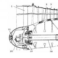 Purpose: basic technical data of the AL 31F engine
 What is severance pay?
 How to number the decisions of the sole founder of an LLC?
 How to fill out a vacation schedule?
 Traffic light concepts, history, purpose Food discounter traffic light
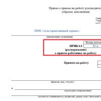 Order for the appointment of the General Director: sample filling, download form
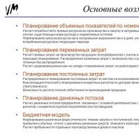 Master of Finance Master of Finance Analysis and Planning