Technical characteristics of sea vessels. Basic tactical and technical characteristics. The ship is a complex engineering and technical floating structure for the carriage of goods and passengers, water industry, mining, sports, as well as
Page 1
M / v "Geulborg" - dry cargo ship, built at the German plant J.J. SIETAS KG HAMBURG Launched from the stocks on 10.10.1994. It is under the supervision of the Register BUREAU VERITAS / 06005E. The shipowner is Esmeralda Shipping Management A.S. (Germany), home port Willemstad, technical operator WAGENBORG (Holland). Main engine type STORK- WARTSILA DIESEL BV. TYPE 8SW 280, 4 STROKE2350 KW / 3193 Hp at 900 RPM. Located aft.
1. Type Dry cargo ship
The name "Geulborg"
Callsign PJNH
2. Year of construction 1994
Register Class BUREAU VERITAS / 06005E 1+ HULL + MACH ICE Class 1B
3. Length overall 89.80 m
Length between perpendiculars 84.99 m
Width 13.60 m
Board height 7.20 m
Draft fully loaded: in salt water 5.70 m
empty Tn - 0.25m Tk - 1.95m
in ballast Тн - 3,35m Тк - 4,20m
4. Displacement: full 5441 t
empty 1139 t
Registered tonnage: GRT 2771 Hg
5. Deadweight 4149.0 t
6. Main power plant:
Type STORK - WARTSILA DIESEL BV. TYPE 8SW 280, 4 STROKE,
Performance 2350 kWt / 3193hp
Fuel consumption on the move, loaded 7.2 t НFO 380
in ballast 6.8 t
in the port 0.35 t
7. Full speed 13.0 knots
Operating speed, laden 9.0 knots
in ballast 11.5 knots
8. Propeller pitch 0.982 m
9. Disk ratio 0.38
10. Speed at full forward speed 720 rpm
11. Steering wheel type semi-balanced
Rudder area 3.75 m2
12. Type of steering gear:
Electro-hydraulic plunger drive driven by one / two pumps.
Providing rudder shifting from 35 ° on one side to 35 ° on the other side.
13. Power steering gear: 4.5 kW
14. Bow thruster: JASTRAM, Type BU40F, 230KW / 304 Hp.
15. Ship power plant
Number and total capacity of generators 750 kW
Marine mains voltage 220 V
16. Radio communication facilities:
COSPAS-SARSAT RT-260M emergency radio beacon
Radar transponder RT-9
Ship earth station SES Inmarsat – A JUE-45A
Receiver NAVTEX NT-900
Terminal of messages SES INM-C H2098A
Radiotelex message terminal H209
VHF radio station RT2048
VHF portable radio station SP3110
DSC VHF modem and 70 channel RM2042 receiver
Scanning DSC distress frequency receiver MF / HF and DSC modem RM2150
On-board communication and broadcasting "INTERCOM" is used as a command broadcasting device and a service intercom system;
17. Crew of 9 people: command personnel - 4 people, rank-and-file personnel - 5 people
Maneuverable characteristics
Table 1.1
The ship's agility when the rudder is shifted by 15º and 35º
|
In ballast |
|||||||||
|
Turning time min-s (VH = 10.6 knots) |
Turning time min-s (VH = 11.5 knots) |
||||||||
Popular on the site:
Selection of equipment, cutting and measuring tools
For cleaning the metal around a crack or hole according to economic parameters and, based on the size of the batch, it is advisable to use a drill, grinder, as well as various tools: steel brush, scraper, file, reduced, chisel, hammer, mechanical scissors. For sealing cracks and overlapping ...
Train road model
The train model, roads (PMD) is one of the most important components of the transportation process model (MPP), created in ASOUP within the framework of the general data bank (BND), and is a set of arrays reflecting information about the trains and operations with them at stations. Composition information ...
Calculation of indicators of passenger traffic in suburban traffic
As for long-distance and local passenger traffic, the following basic quantitative and qualitative indicators are calculated for suburban traffic: 1). The number of passengers carried:, (2.6) where is the number of separate points at which passengers boarding, following in one n ...
1.1. Classification of ships
All vessels are subdivided into transport, fishing, service and auxiliary and technical fleet vessels. Cargo ships are divided into two classes - dry cargo and tanker.
General purpose dry cargo ships are designed for the carriage of general cargo. General cargo is cargo in packaging (in boxes, barrels, bags, etc.) or in separate places (machines, metal castings and rolled products, industrial equipment, etc.) (Fig. 1.1).
Rice. 1.1. Multipurpose vessel
Universal ships are not adapted for the carriage of any particular type of cargo, which does not allow to use the capabilities of the ship to the maximum extent. For this reason, specialized cargo ships are being built and widely used in world shipping, on which the carrying capacity is better used and the time spent in ports under cargo operations is significantly reduced. They are subdivided into the following main types: bulk carriers, container ships, ro-ro ships, lighter carriers, refrigerated, passenger ships and tankers, etc. All specialized ships have their own individual operational characteristics, which requires special additional training from the crew to acquire certain skills for safe transportation of cargo, and also ensuring the safety of the crew and the vessel during the voyage.
Refrigerated vessels (Reefers) are vessels (Fig. 1.2) with an increased speed, intended for the carriage of perishable goods, mainly food, requiring a certain temperature regime in cargo spaces - holds. Cargo holds have thermal insulation, special equipment and small hatches, and the refrigeration unit of the vessel's refrigerated engine room serves to ensure the temperature regime.
Container ships (Container Ships) are high-speed vessels (Figure 1.4) designed for the carriage of various cargoes, pre-packed in special large-capacity containers of standard types. Cargo holds are divided by special guides into cells, into which containers are loaded, and some of the containers are placed on the upper deck. Container ships usually do not have a cargo device, and cargo operations are carried out at specially equipped berths - container terminals. Some types of ships are equipped with a special self-unloading device.
Lighter Ships are ships (Fig. 1.6), where non-self-propelled lighter barges are used as cargo units, which are loaded onto a ship in the port from the water, and unloaded into the water, respectively.
Timber carrying vessel - a vessel for the transportation of timber cargo (Fig. 1.9), including round timber and sawn timber in bulk, in packages and block packages. When transporting timber for the full load of the vessel, a significant part of the cargo is taken to the upper deck (caravan). The deck on timber carriers is fenced with bulwarks of increased strength and equipped with special devices for securing the caravan: wooden or metal stencils installed along the sides of the ship, and transverse lashing.
Service vessels - vessels (Fig. 1.11) for the logistics of the fleet and services that organize their operation. These include icebreakers, towing, rescue, diving, patrol, pilot ships, bunkering ships, etc.
Tankers are tankers designed for transportation in bulk in special cargo spaces - tanks (containers) of liquid cargo. All cargo operations on tankers are carried out by a special cargo system, which consists of pumps and pipelines laid along the upper deck and in cargo tanks. Depending on the type of cargo transported, tankers are divided into:
1. tankers (Tankers) are tankers designed for transportation in bulk in special cargo spaces - tanks (containers) of liquid cargo, mainly oil products (Fig. 1.12);
2. Liquefied Gas Tankers are tankers designed for the carriage of natural and petroleum gases in a liquid state under pressure and (or) at low temperatures, in specially designed cargo tanks of various types. Some types of ships have a refrigerator compartment (Fig. 1.13);
3. Chemical Tankers are tankers designed for the carriage of liquid chemical cargo, the cargo system and tanks are made of special stainless steel, or coated with special acid-resistant materials (Figure 1.14).
 |
1.2. Marine vessel hull design
The design of the hull (Fig. 1.15) is determined by the purpose of the vessel and is characterized by the size, shape and material of parts and parts of the hull, their mutual arrangement, and connection methods.
The hull of a ship is a complex engineering structure, which is constantly subject to deformation during operation, especially when sailing in rough seas. When the top of the wave passes through the middle of the ship, the hull is stretched, while the bow and stern ends hit the crests of the waves, the hull is compressed. A deformation of the general bending occurs, as a result of which the vessel can break (Fig. 1.16). The ability of a vessel to resist general bending is called total longitudinal strength.
External forces, acting directly on individual elements of the ship's hull, cause their local deformation. Therefore, the ship's hull must also have local strength.
In addition, the ship's hull must be watertight, which is ensured by the outer skin and planking of the upper deck, which are attached to the beams that form the set of the ship's hull (the "skeleton" of the ship).
The set system is determined by the direction of most of the beams and is transverse, longitudinal and combined.
With a transverse system of recruitment, the main direction beams will be: in the deck floors - beams, in the side ones - frames, in the bottom ones - flora. Such a recruitment system is used on relatively short ships (up to 120 meters in length) and is most advantageous on icebreakers and ice-going ships, as it provides high hull resistance when the hull is laterally compressed by ice. Midship frame - a frame located in the middle of the estimated length of the vessel.
With a longitudinal set system, in all floors in the middle part of the hull length, the beams of the main direction are located along the ship. At the same time, the extremities of the vessel are recruited according to the transverse dialing system, since at the extremities, the longitudinal system is ineffective. The main beams in the middle bottom, side and deck floors are the bottom, side and bottom longitudinal stiffeners, respectively: stringers, carlings, keel. Floras, frames and beams serve as cross-links.
The use of a longitudinal system in the middle of the ship's length ensures high longitudinal strength. Therefore, this system is used on long boats with high bending moments.
With a combined recruitment system, deck and bottom floors in the middle part of the hull length are recruited according to the longitudinal recruitment system, and the side slabs in the middle part and all overlaps at the ends are recruited according to the transverse recruitment system. This combination of floor set systems allows more
rationally solve the issues of general longitudinal and local strength of the hull, as well as ensure good stability of the deck and bottom sheets when they are compressed.

The combined recruitment system is used on large dry cargo ships and tankers. A mixed ship recruitment system is characterized by approximately the same distances between the longitudinal and transverse beams (Fig. 1.17). In the bow and stern parts, the set is fixed on the stem and sternpost closing the hull.
1.3. Main characteristics of the vessel
Seaworthiness of the vessel
The seaworthiness determines the reliability and structural excellence of the vessel. The seaworthiness includes: buoyancy, stability, unsinkability, controllability, speed, seaworthiness of the vessel.
The survivability of a vessel is the ability of a vessel to maintain its operational and seaworthiness when damaged. It is provided with unsinkability, fire safety, reliability of technical equipment, and crew preparedness.
Buoyancy is the ability of a vessel to float in a desired position relative to the surface of the water under a given load.
Seaworthiness is the ability of a vessel to maintain its basic seaworthiness and the ability to effectively use all systems and devices in accordance with its intended purpose when sailing on sea waves.
The speed of a vessel is its ability to move through the water at a given speed under the action of a driving force applied to it.
Maneuvering characteristics of the vessel
The ship's handling is characterized by two qualities: agility and stability on the course.
Agility is the ability of the vessel to change the direction of movement and move along a curvilinear trajectory pre-selected by the skipper.
Heading stability refers to the ability of the vessel to maintain a straight-line direction of travel in accordance with a given course.
The controllability of the vessel is provided by special controls, the purpose of which is to create a force (perpendicular to the DP), causing the vessel to displace laterally (drift) and turn it around the longitudinal (roll) and transverse (trim) axes.
Controls are subdivided into main and auxiliary ones. Fixed assets - rudders, rotary nozzles, azipods - are designed to ensure the ship's controllability during its movement. The auxiliary means ensure the ship's controllability at low speeds and during coasting with the main engine inoperative. This group includes thrusters of various types, active rudders.
As a result of the impact of the flowing masses of water and wind on the hull, propeller and rudder, even in a calm sea and weak wind, the vessel does not constantly remain on a given course, but deviates from it. The deviation of the vessel from the course when the rudder is straight is called yaw. The yaw amplitude of the vessel in calm weather is small. Therefore, to keep it on the course requires a slight shift of the rudder to the right or left. In strong winds and waves, the stability of the vessel on the course is significantly impaired.
The yaw rate of the vessel is greatly influenced by the location of the superstructure. On those ships where the superstructure is at the stern, the yaw rate increases, since almost always the stern goes "downwind", and the bow - "downwind". If the superstructure is in the bow, then the vessel is evading "from the wind".
The main maneuvering characteristics of the vessel include:
Circulation elements;
The way and time of deceleration of the vessel (inertial properties).
Circulation is a trajectory described by the ship's center of gravity when moving with the rudder deflected at a constant angle (Fig. 1.21). It is customary to divide circulation into three periods: agile, evolutionary and steady-state.
Maneuvering period - the period during which the rudder is shifted to a certain angle. From the moment the rudder begins to shift, the vessel begins to drift and roll in the direction opposite to the rudder shift, and at the same time begins to turn towards the rudder shift. During this period, the trajectory of movement of the center of gravity of the vessel from a straight line turns into a curvilinear one, there is a drop in the speed of the vessel.
Evolutionary period - the period starting from the moment of the end of the rudder shift and continuing until the end of the change in the drift angle,
u u u u p »* J
linear and angular velocities. This period is characterized by a further decrease in speed (up to 30 - 50%), a change in roll to the outer side to 10 0 and a sharp removal of the stern to the outside.
The period of steady circulation is a period that begins after the end of the evolutionary one, characterized by the balance of forces acting on the ship: the propeller stop, hydrodynamic forces on the rudder and hull, centrifugal force. The trajectory of movement of the center of gravity (CG) of the vessel turns into a trajectory of the correct circle or close to it.
Geometrically, the circulation trajectory is characterized by the following elements:
Bo - the diameter of the steady circulation - the distance between the diametrical planes of the vessel on two successive courses, differing by 180 ° at steady motion;
B c - tactical diameter of the circulation - the distance between the positions of the diametral plane (DP) of the vessel before the start of the turn and at the time of changing the course by 180 °;
l 1 - extension - the distance between the positions of the CG of the vessel before entering the circulation to the point of circulation, at which the course of the vessel changes by 90 °;
12 - forward displacement - the distance from the initial position of the ship's CG to its position after turning by 90 °, measured along the normal to the initial direction of movement of the ship;
13 - reverse displacement - the largest displacement of the ship's CG as a result of drift in the direction opposite to the rudder shifting side (the reverse displacement usually does not exceed the ship's breadth B, and on some ships it is absent at all);
T c - circulation period - the time of the ship's turn by 360 °.
Inertial properties of the vessel. In various situations, it becomes necessary to change the speed of the vessel (anchoring, mooring, divergence, etc.). This is due to a change in the operating mode of the main engine or propellers. After which the ship starts to make an uneven movement.
The path and time required to complete the maneuver associated with uneven movement are called the inertial characteristics of the vessel.
Inertial characteristics are determined by time, distance traveled by the vessel during this time, and speed at fixed intervals and include the following maneuvers:
Movement of the vessel by inertia - free braking;
Active braking;
Braking;
Acceleration of the vessel to a given speed.
Free braking characterizes the process of reducing the speed of the vessel under the influence of water resistance from the moment the engine stops to the complete stop of the vessel relative to the water. Usually, the free braking time is considered until the ship loses controllability.
Active braking is braking by reversing the motor. Initially, the telegraph is set to the "Stop" position, and only after the engine speed drops by 40-50%, the telegraph handle is moved to the "Full reverse" position. The end of the maneuver is the stop of the vessel relative to the water.
Acceleration of a ship is the process of gradually increasing the speed of movement from zero to the speed corresponding to a given position of the telegraph.
Load line and groove marks
In order to avoid unacceptable overloading of the vessel from the end of the 19th - the beginning of the 20th centuries. on cargo ships, a load line mark is applied, which determines, depending on the size and design of the ship, the area of its navigation and the season of the year, the minimum permissible freeboard.
The load line is applied in accordance with the requirements of the International Convention on Load Lines, 1966. The load line consists of three elements: the deck line, the Plimsol disc and the draft comb.
 |
A load line mark is applied to the right and left sides in the middle of the vessel. Horizontal stripe applied in the middle of the depicted cargo line
ke disk (Plimsol disk), corresponds to the summer load waterline, i.e. waterlines when a ship is sailing in the ocean in summer at a water density of 1.025 t / m. The designation of the organization that assigned the load line is applied above the horizontal line through the center of the disc.
Load line provisions apply to every ship assigned a minimum freeboard.
Freeboard is the vertical distance measured at the side at the midpoint of the ship's length from the top edge of the deck line to the top edge of the corresponding load line.
The freeboard deck is the uppermost continuous deck not protected from the sea and the weather, which has permanent means of closing all openings in its exposed parts and below which all openings in the sides of the ship are provided with permanent means for watertight closures.
The freeboard assigned to the vessel is fixed by applying on each side of the vessel a mark of the deck line, a mark of the load line and indentation marks indicating the highest draft, up to which the vessel can be maximally loaded under various sailing conditions (Fig. 1.22).
The load line corresponding to the season must not be submerged in the water during the entire period from the moment of leaving the port to arriving at the next port. Ships with load lines on their sides are issued an International Load Line Certificate for a period not exceeding 5 years.
A "comb" is applied to the nose of the disk - a vertical line with load marks extending from it - horizontal lines to which the vessel can submerge under various sailing conditions:
Summer load line - L (Summer);
Winter load line - З (Winter);
Winter load line for the North Atlantic - ZSA (Winter North Atlantic);
Tropical load line - T (Tropic);
Load line for fresh water - P (Fresh);
Tropical brand for fresh water - TP (Tropic Fresh).
Vessels adapted for the transport of timber are additionally supplied with a special timber load line located at the stern of the disk. This mark allows for a slight increase in draft when the ship is carrying timber on an open deck.
Recess marks are used to determine the draft of the vessel. Graduations are applied to the outer skin of both sides of the vessel in the area of the stem, stern and on the midship frame (Fig. 1.23).
The indentation marks are marked with Arabic numerals 10 cm high (the distance between the bases of the digits is 20 cm) and determine the distance from the current waterline to the lower edge of the horizontal keel.
 |
Until 1969, the marks of the recess on the left side were applied in Roman numerals, the height of which was 6 inches. The distance between the bases of the numbers is 1 foot (1 foot = 12 inches = 30.48 cm; 1 inch = 2.54 cm).
Rice. 1.23. Recess marks: in the left picture, the draft is 12 m 10 cm; on the right - 5 m 75 cm
Stability
Stability is the ability of a vessel, brought out of equilibrium by an external influence, to return to it after the termination of this influence. The main characteristic of stability is the restoring moment, which must be sufficient for the vessel to withstand the static or dynamic (sudden) action of heeling and trimming moments arising from the displacement of loads, under the influence of wind, waves and other reasons. The heeling (trimming) and restoring moments act in opposite directions and are equal at the equilibrium position of the vessel.
A distinction is made between lateral stability, which corresponds to the inclination of the vessel in the transverse plane (roll of the vessel), and longitudinal stability (trim of the vessel).
Metacenter - the center of curvature of the trajectory along which the center of the value C moves during the inclination of the vessel (Fig. 1.24). If the inclination occurs in the transverse plane (roll), the metacentre is called transverse, or small, with inclination in the longitudinal plane (trim) - longitudinal, or large. Accordingly, there are transverse (small) r and longitudinal (large) R metacentric radii, representing the radii of curvature of the trajectory C with roll and differential.
Metacentric height (m.h.) - the distance between the metacentre and the center
 |
the gravity of the vessel. M.V. is a measure of the initial stability of the ship, which determines the restoring moments at low heel or trim angles. With increasing m.v. the stability of the vessel is increased. For the positive stability of the vessel, it is necessary that the metacentre is above the CG of the vessel. If m. In. negative, i.e. the metacentre is located below the ship's CG, the forces acting on the ship form not a restoring, but a heeling moment, and the ship floats with an initial heel (negative stability), which is not allowed.
Unsinkability
Unsinkability is the ability of a ship to maintain buoyancy and stability when one or more compartments are flooded, formed inside the ship's hull by watertight bulkheads, decks and platforms.
The flow of seawater into the ship's hull, as a result of its damage or deliberate flooding of the compartments, leads to a change in the characteristics of buoyancy and stability, controllability and propulsion. The redistribution of buoyancy forces along the length of the ship causes additional stresses in the ship's hull, which must maintain sufficient strength at the same time.
Structurally, unsinkability is provided by dividing the ship's hull into a number of compartments using watertight bulkheads, decks and platforms. The deck to which the main watertight bulkheads reach is called the bulkhead deck. Structurally, the vessel's unsinkability is also ensured by the arrangement of drainage systems, measuring pipes, watertight closures, etc. on the vessel.
The performance of the vessel
Performance determines the transport capabilities and economic performance of the vessel. They are determined by its carrying capacity, cargo and passenger capacity, speed, maneuverability, range and autonomy of navigation.
Carrying capacity - the weight of various types of cargo that can be transported by the vessel, provided that the design landing is maintained. There is a net payload and deadweight.
Net payload is the total mass of the payload transported by the vessel, i.e. weight of cargo in holds and weight of passengers with luggage and fresh water and provisions intended for them, weight of caught fish, etc., when loading the vessel according to the design draft.
Deadweight (full carrying capacity) - represents the total mass of the payload transported by the vessel, constituting the net carrying capacity, as well as the mass of fuel supplies, boiler water, oil, crew with luggage, provisions and fresh water for the crew when loading the vessel according to the design draft. If a loaded vessel takes on liquid ballast, the mass of this ballast is included in the vessel's deadweight.
1. Linear characteristics of the vessel:
The linear characteristics in the 1st stage include the overall dimensions of the vessel:
Lex is the maximum or maximum length of the vessel (m), measured between the extreme points of the bow and stern ends of the vessel;
- L is the length of the vessel (m) or the distance measured at the level of the summer load waterline from the leading edge of the stem to the axis of the rudder stock, or 96% of the length of the vessel measured at this waterline from the leading edge of the stem to the extreme edge of the stern of the vessel, as seen from what is more;
- Milestone - the largest width of the vessel (m), measured on the mid-frame between the outer edges of the frames;
- B - the width of the vessel at the waterline (m), measured amidships, in the plane of the summer cargo waterline, between the outer edges of the frames;
- D - board height (m). The vertical distance measured amidships from the top of the horizontal keel to the top of the upper deck beam at side.
On ships having a rounded upper deck-to-side connection, the depth of the ship is measured to the point of intersection of the extended upper deck and side lines, as if the connection were angular; d- draft of the vessel (m). Distance measured vertically amidships from the top of the horizontal keel to the corresponding waterline.
In addition to the above-mentioned draft of the ship amidships, the draft of the ship is distinguished by the bow d n and the stern d k, which are usually measured by the marks of the recess, applied on the sides of the ship at its extremities.
Recess marks are applied on the starboard side in decimetres and denoted by Arabic numerals, on the left side - in feet and denoted by Roman numerals.
The height of the numbers on the port side and the vertical distance between them are equal to 1 foot.
The height of the numbers on the starboard side and the distance between them is 1 dm.
The measured draft of the vessel according to the indentation marks gives the vertical distances between the lower edge of the horizontal keel and the waterline along which the vessel floats, in those places along its length where the marks are applied.
The amidships or average draft is calculated as the half-sum of the bow and stern draft.
The difference in draft between bow and stern is called the trim of the vessel. If the bow of the ship is submerged in the water more than the stern, then the ship is said to be trimmed to the bow, and vice versa.
2. Volumetric characteristics of the vessel:
- the cargo capacity of the vessel W (m 3) the volume of all ship spaces intended for the carriage of cargo. Distinguish between cargo capacity when transporting piece cargo - in bales and cargo - in bulk (in grain);
- bale cargo capacity of the vessel Wк (m 3), or the volume of all cargo spaces between the inner edges of protruding structures (frames, beams, carlings, etc.) and their protecting parts;
- the cargo capacity of the vessel in bulk Wz (m 3) - the total volume of all available free volumes in the cargo spaces. The cargo capacity of a vessel in bulk is always greater than the cargo capacity in bales;
- specific cargo capacity of the vessel (m 3 / t), or cargo capacity of the vessel per 1 ton of its net cargo capacity;
w = W / ∆h.
For the calculation of charges levied on vessels for the use of canals, pilotage services, docking, etc., as well as for statistical accounting of the fleet, the so-called gross tonnage of the vessel and the net tonnage of the vessel are established, which are measured in registered tons (1 reg.t . = 100 cubic feet or 2.83 m 3).
Container capacity - measured in TEU (TEU "S). TEU - twenty feet equivalent unit" s), that is, how many 20-foot containers the ship can place in the holds and on the deck. 700 - bulk container ship, container capacity of 700 twenty-foot containers, in place of 2 twenty-foot containers, as a rule, it is possible to put 1 forty-foot container and vice versa.
On Ro-Ro vessels, the cargo capacity is indicated in thousands of m 3, for example, Ro / 60 means a capacity of 60,000 m 3.
3. Cargo characteristics of the vessel.
The cargo characteristics of the vessel include the following data about it:
- specific cargo capacity,
- coefficient of structural unevenness of holds,
- number and size of hatches, lumen ratio,
- number of decks and their area, permissible deck loads,
- the number and capacity of the ship's lifting equipment,
- technical means of ventilation and microclimate control in cargo spaces.
Since the specific tonnage of a ship is related to its net tonnage, it can be considered constant only for a given net tonnage of the ship.
However, for practical purposes, net tonnage can be calculated assuming 50% of the ship has stock: ∆ = ∆w -0.5Σ.
Thus, the conditional net carrying capacity will be constant, which makes it possible to use the specific cargo capacity with sufficient accuracy.
Comparison of the specific cargo capacity with the specific loading volume of cargo makes it possible to judge the possibility of using the carrying capacity and cargo capacity of the vessel when loading it with this or that cargo.
For oil tankers, another qualitative characteristic of the vessel is more important - the specific carrying capacity of the tanker.
Specific tonnage of a tanker - shows how many tons (kg) fall on 1 m 3 of capacity.
In principle, the specific cargo capacity is provided for in the design of the vessel and, depending on the purpose of the vessel (for which cargo), is distributed as follows:
Ore carriers 0.8-1.0 m / t, bulk carriers 1.2-1.3 m 3 / t, container ships 1.2-4.0 m 3 / t, tankers 1.3-1.4 m 3 / t , multi-purpose vessels 1.5-1.7 m 3 / t, timber trucks 2.0-2.2 m 3 / t, Ro-ro boats 2.5-4.0 m 3 / t.
International Convention for Tonnage Measurement of Ships 1969
Purpose of the Convention:
- the measurement results are expressed in m 3;
- to minimize the advantages of shelter decks and the like.
The following new terms and their designations have been introduced in the Convention:
- gross tonnage - GT in m 3 (instead of BRT in registered tons);
- net tonnage (Netto gross tonnage) - NT in m 3 (instead of NRT in registered tons).
Under the new rules of the 1969 Convention, as well as under the current measurement rules, the gross tonnage GT characterizes the size of the ship and the total volume of its premises, and the net tonnage NT - the volume of premises intended for generating commercial income.
However, since the 1969 Convention affects and infringes on the commercial interests of many countries, its entry into force is delayed.
Registered tonnage, a conditional indicator of the volume of the ship's premises protected from the sea. The unit of measurement is, as indicated above, the register tonne, equal to 100 cubic meters. feet (2.83 m 3), that is, the register ton is a volumetric quantity. Registered tonnage is used to compare the size of ships and determine the value of various port dues, as well as for static accounting of tonnage.
Registered tonnage is subdivided into:
Gross tonnage is the volume of all spaces of the ship below deck and in superstructures minus the volume: ballast tanks, wheelhouse, space on deck for auxiliary machinery, galley, skylights, etc.
Net register tonnage is the volume of premises used for the carriage of goods and passengers, that is, used for commercial purposes, and is mainly used for calculating port dues and taxes. It is obtained as a result of excluding the volume of residential and office premises from the gross register tonnage.
rooms, tiller and chain boxes, navigational rooms, ballast water outside the double bottom space, rooms for boilers and auxiliary mechanisms outside the engine room.
Based on the measurement, the Register issues a document called a tonnage certificate.
The number and capacity of the ship's cargo vehicles. The lifting capacity of ship booms and cranes is usually 3-10 tons. The lifting capacity of cargo booms and cranes is of great importance, since it determines the weight of the hoists, which, in turn, affects the intensity of cargo operations. Modern multipurpose vessels are equipped with cranes with a lifting capacity of up to 35-40 tons, which allows them to independently reload containers. In addition to conventional arrows, ships are armed with heavy arrows with a carrying capacity of up to 60-120 tons for loading heavy cargo in ports and roadstead points.
The complex of cargo equipment for Ro-Ro vessels should include: 2 forklift trucks with a lifting capacity of 40 tons and 2 tractors for towing rolling cargo.
Ore carriers, bulk carriers and container carriers (with the exception of feeder carriers) do not have ship reloading facilities, since they are handled mainly at specialized transshipment complexes (terminals).
Tankers have at least two cargo pumps with a capacity of at least 10% of the deadweight per hour. Cargo pumps are only designed to drain cargo from cargo tanks. Tankers are loaded by onshore pumps.
Uneven holds - the capacity of individual holds of sea-going vessels is not the same, which leads to uneven distribution of cargo among the holds, while handling them simultaneously, the largest hold limits the time of completion of cargo operations, reducing the level of intensity of cargo handling of the vessel as a whole.
Coefficient of structural unevenness of holds
The value of the coefficient fluctuates for most vessels within the range of 0.6-0.9, the lower the coefficient, the lower the rate of cargo operations, therefore, the vessel's parking under cargo operations increases.
The number and size of hatches are the most important factor in determining the duration of cargo operations.
The number of hatches determines how many strokes can be used to load and unload the vessel, which has a decisive influence on the speed of its processing.
The dimensions of the hatches determine the degree of convenience, and therefore the speed of loading and unloading, with a wide opening of the deck of the vessel, they significantly reduce the horizontal movement of cargo in the holds, the most laborious process limiting the loading process.
The degree of convenience and adaptability of the vessel to the performance of cargo operations is characterized by the lumen ratio, which is the ratio of the total volume of cargo spaces located under the hatch clearance to the total cargo capacity of the vessel.
The number of decks and their area.
Permissible deck loads. - The depth of the hold is important on single-deck vessels, as it allows the transport of packaged cargo in several tiers and at the same time limits the carriage of cargo consisting of high cargo packages.
However, most of the general cargo has restrictions on the stacking height (the number of tiers) in order to protect the lower tiers from crushing.
Therefore, on universal ships, an intermediate deck is installed - a twin deck, with the help of which the cargo is protected from crushing and the pressure of the cargo on the hold deck is reduced.
In addition, the twin-deck deck increases the total area of cargo decks, which makes it possible to accommodate a larger number of bulky cargo packages (oversized) on the ship, which are transported in 1, maximum 2 tiers.
For Ro-Ro vessels, deck area is the most important cargo characteristic.
In order to increase the area of decks, in addition to fixed decks, they are equipped with removable or suspended intermediate decks.
Permissible deck loads - tons per sq. meter (t / m 2), basically, should correspond to the height of the cargo space:
σadm g 0.9H (t / m 2),
where H is the height of the hold.
On Ro-Ro vessels, each deck must withstand at least a double TEU load, weighing 25 tons. For ore carriers, the permissible load is 18-22 tons / m2. Universal ships: the deck of the hold, depending on the height of the hold, is 6-12 t / m, twin deck 3.5-4.5 t / m, upper deck 2-2.5 t / m 2, cargo hatch covers 1.5 -2.0 t / m 2. Timber trucks: upper deck and cargo hatch covers 4.0-4.5 t / m 2. Container ships: deck of holds at least 25 tons TEU in 6 tiers.
Technical means of ventilation and microclimate control of cargo spaces
According to the degree of equipment with technical means of ventilation, ships are divided into three groups:
- having natural forced ventilation;
- equipped with a mechanical ventilation system;
- equipped with an air conditioning system in cargo spaces.
On ships equipped with natural forced ventilation, air is supplied to the holds and twin decks through a system of deflectors and air ducts.
The performance of natural forced ventilation can often be insufficient to ensure the safe transportation of goods in difficult hydrometeorological conditions, especially at long distances. To increase the air exchange of cargo spaces and supply outside air to them, a mechanical ventilation system is used on ships.
Mechanically ventilated vessels are equipped with an air distribution system and electric fans.
Air supply to the ship's hold is provided by fans, the performance of which depends on the set rate of air exchange. For ordinary universal ships, a 5-7-fold air exchange per hour is sufficient, and on ships that transport fruits, vegetables and other specific cargo, it is necessary to provide 15-20-fold air exchange per hour.
4. Vessel speed and cruising range:
The speed of the vessel is the most important operational characteristic of the vessel, which determines its carrying capacity and the timing of the delivery of goods.
The speed depends on the power of the main engine and the hull contours. The choice of speed when designing a vessel can only be decided taking into account the fuel consumption of the main engine, the carrying capacity and the cargo capacity of the vessel. The take off speed is determined on the gauge line when the engine is running at full power (maximum).
The technical or passport speed is set when the main engine is running at 90% of the maximum power.
Economical speed - the speed of the vessel at which the minimum fuel consumption per unit of travel (one mile).
Typically, this speed is 60-70% of the technical speed. It is used if the ship has a reserve of time to arrive at the port of destination or, due to some circumstances, does not have an adequate supply of fuel.
The range and autonomy of navigation - depends on the capacity of the fuel tanks, i.e. 100% of the fuel supply at an economical speed:
qfuel
Lmili = 100% (qfuel / Veconomic)
According to the foreign press, the share of fuel costs in the total operating costs of the vessel is over 65%. Currently, the speed of many high-speed vessels has been reduced to 40-50%, due to a sharp rise in the price of oil products.
5. Type and power of the main engine, fuel type:
By the type of engine, ships are subdivided into steamers with piston engines, motor ships with diesel engines, steam and gas turbine ships, diesel electric ships and turbo electric ships, nuclear powered ships, etc.
The most widespread are ships with low-speed diesel engines of high power, with low specific fuel consumption, however, having rather significant dimensions and weight.
At present, ships have installed relatively small and light medium-speed main engines with two or more such engines operating on the propeller shaft through a reduction gear.
As a result of improvements, engines of this class have approached the low-speed ones in terms of service life and reliability, but at the same time they are much lighter and take up less space on the ship.
General arrangement of ships Ketnikov K.N.
§ 10. The tactical and technical (or combat) qualities of the ships of the Navy
The tactical and technical (or combat) qualities of ships ensure the fulfillment of the tasks assigned to us, just as the operational qualities ensure compliance with the purpose of civil ships. These qualities are:
combat effectiveness of a ship - the ability to strike at the enemy with the aim of destroying it, while maintaining or maintaining its weapons and technical means;
survivability of a ship - its ability to withstand combat and navigational damage, the effects of fires, atomic and chemical weapons. The fight for the survivability of a ship also means the fight for unsinkability, extinguishing fires, repairing damage to the hull and combat installations, and switching power assets and their lines.
The rest of the combat (or tactical and technical) qualities of ships are already familiar to us: speed, maneuverability, cruising range, autonomy and habitability.
From the book Prospect 705 Small High-Speed Automated Fighter Submarine (705K) the author author unknownTactical and technical elements of the submarine pr. 705 Displacement, t: - surface 2300 - underwater 3 100 Main dimensions, m: - length naib 81.4 - width of the hull naib 10.0 - draft at design waterline 7.6 Power plant: - type nuclear Steam generating plant: - type of. ... OK-550 - composition 1 AR
From the book The Battleship "PETER THE GREAT" the author Arbuzov Vladimir VasilievichTactical and technical elements of Project 705K submarine Displacement, t: - surface 2300 - underwater 3100 Main dimensions, m: - length naib 81.4 - width of the hull naib 10.0 - width along stabilizers 13.5 - draft according to design waterline 7.6 Depth of immersion , m: - working 350 - maximum 420
From the book Rockets and Spaceflight by Leigh WillieTactical and technical data of the training ship "Peter the Great" Back in early August 1907, the Naval Minister, having familiarized himself with the progress of work and the degree of readiness of the new training ship *, ordered in early September to introduce it into a one and a half month campaign for testing
From the book Heavy Tank T-10 author Mashkin A. From the book History of the Russian machine gun the author Monetchikov S. B.TACTICAL AND TECHNICAL DATA OF VARIOUS TYPES OF MISSIONS AND MISSION WEAPONS.
From the book Back to the Future author Shaidurov IlyaTACTICAL AND TECHNICAL DATA OF VARIOUS TYPES OF MISSIONS AND MISSION WEAPONS.
From the author's bookTACTICAL AND TECHNICAL DATA OF VARIOUS TYPES OF MISSIONS AND MISSION WEAPONS. UNITED KINGDOM There is almost no published data on the development of rockets and rockets in the UK. However, it must be admitted that not much has been done. It is officially reported that all developments
From the author's bookTACTICAL AND TECHNICAL DATA OF VARIOUS TYPES OF MISSIONS AND MISSION WEAPONS.
From the author's bookTACTICAL AND TECHNICAL DATA AND TABLES OF ROCKET LAUNCHES
From the author's bookTACTICAL AND TECHNICAL CHARACTERISTICS OF HEAVY TANKS Self-propelled launcher SM-SP21 of the RT-20P missile based on the chassis of the T-10 heavy tank Self-propelled launcher SM-SP21 of the "Gnome" missile based on the chassis of the T-10 T-10 heavy tank in the Museum of Military Glory, Saratov T-10A at the military
From the author's bookTable 1 Tactical and technical characteristics of assault rifles, carbines and light machine guns for the "intermediate" cartridge Name Fedorov assault rifle mod. 1916 AK AKS SKS AKM AKMS RPK RPKS Caliber (mm) 6.5 7.62 7.62 7.62 7.62 7.62 7.62 Weight (kg) 4.4 4.86 4.86 3.9 3.6 3 , 8 5.6 5.9 Overall length
From the author's bookTable 2 Tactical and technical characteristics of assault rifles and light machine guns for "low-impulse" cartridge Name AK-74 AKS-74 AKS-74U RPK-74 RPKS-74 AK-74M RPK-74M Caliber, mm 5.45 5.45 5.45 5.45 5.45 5 , 45 5.45 Weight, kg 3.6 3.67 3.0 5.46 5.61 3.6 5.46 Overall length, mm 940 940 730 1060 1060 940 1065 Length with folded.
From the author's bookTable 3 Tactical and technical characteristics of machines for "low-impulse" cartridge Name AK101 AK102 AK103 AK-104 AK-105 AKK-971 AN-94 A-91 A-91 A-91 Caliber, mm 5.56 5.56 7.62 7.62 5.45 5 , 45 5.45 5.45 5.56 7.62 Weight, kg 3.8 3.6 3.8 3.6 3.5 3.3 4.3 1.75 1.75 1 * 75 Overall length, mm 943 824 943 824 824 965 943 604 604 604 Length with folded
From the author's bookTable 4 Tactical and technical characteristics of machines for special cartridges Name APS 9 А-91 ВСК-94 ВСС АС СР-3 "Whirlwind" Caliber, mm 5.66 9 9 9 9 9 Weight, kg 2.46 2.55 3.34 3.41 2.96 2.0 Overall length, mm 823 604 900 894 875 640 Length with folded butt, mm 615 384 - - 615 396 Barrel length,
From the author's bookTable 5 Tactical and technical characteristics of weapons Baryshev AB -5.45 AV-7.62 AVK KPB AR GB Weight, kg 3.4 3.6 4.7 13.2 15.3 Overall length, mm 865 960 1000 1455 950 Length with folded stock, mm 645 710 750 1215 700 Barrel length, mm 415 415 500 750 300 Bullet muzzle velocity, m / s 900 715 800 840 185 Rate of fire,
From the author's bookThe performance characteristics of the KM2K knife Total length - 305 mm Total length with scabbard - 327 mm Blade length - 172 mm Blade width - 30 mm Blade thickness - 4.6 mm Scabbard dimensions: length x width - 196 x 30 mm Knife weight - 303 g Knife weight with scabbard - 516 g Blade material -
Send your good work in the knowledge base is simple. Use the form below
Students, graduate students, young scientists who use the knowledge base in their studies and work will be very grateful to you.
Posted on http://www.allbest.ru/
1. Introduction
2. Performance characteristics
2.1 Main dimensions of the vessel
2.2 Displacement
2.3 Carrying capacity
2.4 Capacity
2.5 Ship speed
3. Seaworthiness
3.1 Buoyancy
3.2 Stability
3.3 Stroke
3.4 Controllability
3.6 Unsinkable
4. Sources
Introduction
The ship is a complex engineering and technical floating structure for the carriage of goods and passengers, water industry, mining, sports, as well as for military purposes.
In the Law of the Sea, a seagoing vessel is understood as a self-propelled or non-self-propelled floating structure, that is, an object artificially created by man, intended for permanent stay at sea in a floating state. For the recognition of a structure as a ship, it does not matter whether it is equipped with its own engine, whether the crew is on it, it is moving or is mainly in a stationary floating state. The same definition, apart from the sea, applies to inland water bodies and rivers.
As an engineering structure intended for specific purposes, the vessel has operational and seaworthy characteristics.
Performance characteristics
Main dimensions of the vessel
The main dimensions of the vessel are called its linear dimensions: length, width, depth and draft.
Diametral plane (DP) - vertical longitudinal plane of symmetry of the theoretical surface of the ship's hull.
The plane of the midship frame is a vertical transverse plane passing in the middle of the ship's length, on the basis of which the theoretical drawing is built.
Under the frame (Шп) is understood in the theoretical drawing the theoretical line, and in the design drawings - the practical frame.
Constructive waterline (KVL) - the waterline corresponding to the estimated total displacement of the vessels.
Waterline (VL) - the line of intersection of the theoretical surface of the hull with a horizontal plane.
Aft perpendicular (CP) - the line of intersection of the diametrical plane with the vertical transverse plane passing through the point of intersection of the stock axis with the plane of the structural waterline; CP on the theoretical drawing coincides with the 20th theoretical frame.
The nasal perpendicular (NP) is the line of intersection of the diametral plane with the vertical transverse plane passing through the extreme nasal point of the structural waterline.
Main plane - the horizontal plane passing through the lowest point of the theoretical surface of the body without protruding parts.
In drawings, descriptions, etc., dimensions are given for length, width and height.
The length of the vessels is determined parallel to the main plane.
Maximum length L nb - the distance measured in the horizontal plane between the extreme points of the bow and stern ends of the hull without protruding parts.
Length along the constructive waterline L kvl - the distance measured in the plane of the constructive waterline between the points of intersection of its bow and stern with the diametrical plane.
Length between perpendiculars L PP - the distance measured in the plane of the structural waterline between the fore and aft perpendiculars.
Length at any waterline L ow is measured as L sql
Length of the cylindrical insert L c - the length of the ship's hull with a constant section of the frame.
The length of the nasal cusp L n - is measured from the nasal perpendicular to the beginning of the cylindrical insert or to the bulkhead of the largest section (for ships without a cylindrical insert).
The length of the stern edge L k - is measured from the end of the cylindrical insert or frame of the largest section - the end of the stern part of the waterline or other designated point, for example, the stern perpendicular. Breadth measurements of vessels are measured parallel to the main and perpendicular to the centerline.
Maximum width B nb - the distance measured between the extreme points of the body, excluding protruding parts.
Width at the midship frame B is the distance measured at the midship frame between the theoretical surfaces of the sides at the level of the design or design waterline.
Width at design waterline V kvl - the largest distance measured between the theoretical surfaces of the sides at the level of the structural waterline.
Width over VL V vl is measured as V sq.
Height dimensions are measured perpendicular to the base plane.
Depth H is the vertical distance measured on the midship frame from the horizontal plane passing through the point of intersection of the keel line with the plane of the midship frame to the side line of the upper deck.
Height of the side to the main deck Н Г П - the height of the side to the uppermost continuous deck.
Depth to twin deck H TV - depth to deck below the main deck. If there are several twin decks, then they are called the second, third, etc. deck, counting from the main deck.
Draft (T) - vertical distance measured in the plane of the midship frame from the main plane of the structural or design waterline.
Draft bow and stern draft Т n and Т к - are measured on the bow and stern perpendiculars to any waterline.
Average draft T avg - measured from the main plane to the waterline in the middle of the ship's length.
Fore and aft sheerness h n and h k - smooth rise of the deck from the midsection to the bow and stern; the amount of lift is measured at the fore and aft perpendiculars.
Kill beams h b - the difference in height between the edge and the middle of the deck, measured at the widest point of the deck.
Freeboard F is the vertical distance measured at the side of the ship midway from the top of the deck line to the top of the corresponding load line.
If necessary, other dimensions are indicated, such as, for example, the highest (overall) height of the vessel (height of a fixed point) from the load waterline during an unladen voyage for passage under bridges. Usually, however, they are limited to indicating the length - the largest and between the perpendiculars, the width at the mid-frame, the side height and the draft. In cases of application of international Conventions - on the safety of life at sea, on load lines, measurement, classification and construction of ships - they are guided by the definitions and dimensions established in these Conventions or Rules.
Displacement
Displacement is one of the main characteristics of the vessel, which indirectly characterizes its size.
The following displacement values are distinguished:
Mass or weight and volume,
Surface and underwater (for submarines and submarines),
· Light displacement, standard, normal, full and maximum.
The full displacement is equal to the sum of the empty displacement and the deadweight.
Displacement of a vessel - the amount of water displaced by the underwater part of the vessel's hull. The mass of this amount of water is equal to the weight of the entire vessel, regardless of its size, material and shape. (According to Archimedes' law)
Ш Mass (weight) displacement is the mass of a ship afloat, measured in tons, equal to the mass of water displaced by the ship.
Since during operation the mass of the vessel can vary widely, in practice two concepts are used:
Displacement in full load D, equal to the total mass of the ship's hull, all mechanisms, devices, cargo, crew passengers and ship's stores at the highest permissible draft;
Empty displacement D0, equal to the mass of the vessel with equipment, permanent spare parts and supplies, with water in boilers, machinery and pipelines, but without cargo, passengers, crew and without fuel and other supplies.
W Volumetric displacement - the volume of the underwater part of the vessel below the waterline. With a constant weight displacement, the volumetric displacement changes depending on the density of the water.
That is, the volume of the liquid displaced by the body is called the volumetric displacement.
The center of gravity of the volumetric displacement W is called the center of displacement.
Standard displacement - the displacement of a fully equipped ship (vessel) with a crew, but without supplies of fuel, lubricants and drinking water in the tanks.
Normal displacement is a displacement equal to the standard displacement plus half of the fuel, lubricants and drinking water in the tanks.
Full displacement (loaded displacement, full load displacement, designated displacement) - a displacement equal to the standard displacement plus full reserves of fuel, lubricants, drinking water in tanks, cargo.
Displacement reserve is an excess addition to the ship's mass taken during design to compensate for the possible excess of the mass of its structure during construction.
The largest displacement is a displacement equal to the standard displacement plus the maximum reserves of fuel, lubricants, drinking water in tanks, cargo.
Submarine displacement - the displacement of a submarine (bathyscaphe) and other submarines in a submerged position. Exceeds surface displacement by the mass of water taken when immersed in the main ballast tanks.
Surface displacement - the displacement of a submarine (bathyscaphe) and other submarines in a position on the surface of the water before submersion or after surfacing.
Carrying capacity
Carrying capacity is one of the most important operational characteristics - the mass of cargo for the transportation of which the vessel is designed - the weight of various types of cargo that the vessel can carry, provided that the design landing is maintained. Measured in tons. There is a net payload and deadweight.
Net Payload (Payload) is the total mass of the payload transported by the ship, i.e. weight of cargo in holds and weight of passengers with luggage and fresh water and provisions intended for them, weight of caught fish, etc., when loading the vessel according to the design draft.
Deadweight (full load) - DWT - deadweight tonnes. It is the total mass of the payload transported by the ship, constituting the net carrying capacity, as well as the mass of fuel, water, oil, crew with luggage, provisions and fresh water for the crew when the ship is loaded at the design draft. If a loaded vessel takes on liquid ballast, then the mass of this ballast is included in the vessel's deadweight. Deadweight at summer load line draft in sea water is an indicator of the size of a cargo ship and its main operational characteristic.
The carrying capacity should not be confused with the cargo capacity, and even more so with the registered capacity (registered cargo capacity) of the vessel - these are different parameters measured in different quantities and having different dimensions.
Capacity
In addition to determining the carrying capacity of a vessel in weight units (now usually in metric tons) and measuring the total weight of a vessel by a displacement parameter, there is a historical tradition of measuring the internal volume of a vessel. This parameter is only used for civilian ships.
The capacity of the ship is the volumetric characteristic of the premises of the ship. Cargo capacity and registered tonnage should not be confused. There is also a “passenger capacity” parameter for passenger and cargo-passenger ships.
The parameters of capacity (cargo capacity), carrying capacity (including deadweight) and displacement are not related to each other and, in the general case, are independent (although for one class of ships there are coefficients that indirectly relate one parameter to another).
Gross tonnage (BRT) is the total capacity of all watertight enclosed spaces; thus, it indicates the total internal volume of the ship, which includes the following components:
The volume of the premises under the measurement deck (the volume of the hold under the deck);
The volume of the premises between the measurement and upper decks;
The volume of enclosed spaces located on the upper deck and above it (superstructure);
The amount of space between the hatch coamings.
The gross tonnage does not include the following enclosed spaces if they are intended and suitable exclusively for the named purposes and are used only for this:
Premises containing power and electric power plants, as well as air intake systems;
Rooms for auxiliary machinery that do not serve the main engines (for example, rooms for refrigeration plants, distribution substations, elevators, steering gears, pumps, processing machines on fishing vessels, chain boxes, etc.);
A vessel that has openings in the upper deck without strong watertight closures (measuring hatches and openings) is called a shelter boat or a hinged deck vessel; it has a lower register capacity due to such openings. Closed internal volumes in open spaces that have strong waterproof closures are included in the measurement. A condition for excluding open spaces from measurement is that they do not serve to accommodate or serve the crew and passengers. If the upper deck of double or multi-deck ships and the bulkheads of the superstructures are fitted with strong watertight closures, the interdeck space below the upper deck and the spaces of the superstructures are included in the gross tonnage. Such vessels are called full-range vessels and have a maximum allowable draft.
Net capacity (NRT) is the net volume to accommodate passengers and cargo, i.e. the sales volume. It is formed by subtracting the following components from the gross tonnage:
Premises for the crew and boatmasters;
Navigation rooms;
Premises for skipper's supplies;
Ballast water tanks;
Machine room (power plant premises).
Deductions from gross tonnage are made according to certain rules, in absolute terms or as a percentage. The deduction condition is that all these spaces are included in the gross tonnage first. In order to be able to verify whether the tonnage certificate is genuine and whether it belongs to this particular vessel, it indicates the dimensions of the identity (identification dimensions) of the vessel, which are easy to verify.
The cargo capacity of a ship is the volume of all holds in cubic meters, cubic feet, or 40 cubic feet "barrels". Speaking about the capacity of holds, the capacity is distinguished by piece (bales) and bulk (grain) cargo. This difference arises from the fact that in one hold, due to floors, frames, stiffeners, bulkheads, etc., bulk cargo can be placed more than piece cargo. The general cargo hold accounts for approximately 92% of the bulk cargo hold. The calculation of the vessel's capacity is carried out by the shipyard; the capacity is indicated on the tank diagram, and it has nothing to do with the official measurement of the vessel. Specific cargo capacity is the ratio of the holding capacity to the payload mass. Since the mass of the payload is determined by the mass of the required operating materials, the specific cargo capacity is subject to insignificant fluctuations. General cargo cargo ships have a specific tonnage of approximately 1.6 to 1.7 m3 / t (or 58 to 61 cubic feet).
Ship speed
Speed is one of the most important operational characteristics of the vessel and one of the most important tactical and technical characteristics of the vessel, which determines the speed of its movement.
The speed of vessels is measured in knots (1 knot is equal to 1.852 km / h), the speed of inland navigation vessels (river, etc.) - in kilometers per hour.
There are the following types of vessel speed:
Ш The absolute speed of the ship is the speed measured by the distance traveled by the ship per unit of time relative to the ground (stationary object) along the line of the ship's path.
The safe speed of the ship is the speed at which appropriate and necessary action can be taken to avoid collision.
Ш Cruising (for warships, also the combat economic speed of a ship) is a speed that requires a minimum fuel consumption per mile traveled with a normal displacement and operation of naval and military equipment in a mode that ensures the full technical readiness of the main mechanisms for the development of full combat speed.
Ш The general speed of the ship is measured by the distance traveled by the ship per unit of time according to the general course.
Ш Permissible vessel speed - the established maximum speed, limited by the conditions of the combat mission being performed, the situation or the rules of navigation (when trawling, towing, in waves or shallow water, in accordance with the rules of the roadstead service or a mandatory regulation on the port)
Ш The highest speed of the vessel (or maximum) develops when the main power plant (main power plant) of the vessel is in forced mode, while ensuring the full combat readiness of the vessel. Prolonged forcing of the power plant can lead to its failure and loss of speed, as a result of which the vessel is resorted to reaching the highest speed in exceptional cases.
Ш The lowest speed of the vessel (or minimum) - the speed at which the vessel can still be kept on course (controlled with the help of the rudder).
W The relative speed of a vessel is measured by the distance traveled by the vessel per unit of time relative to the water.
Ш The full combat speed of the vessel (or full speed) is achieved when the power plant is operating in full power mode (without afterburner) with the simultaneous operation of all combat and technical means of the vessel, ensuring the full combat readiness of the vessel.
Ш Economic speed of the vessel (or technical and economic) - the speed achieved when the power plant is operating in the economic mode. At the same time, the task of the lowest fuel consumption per mile traveled is achieved while simultaneously ensuring the established combat readiness and domestic needs of the vessel.
Ш Squadron speed of a vessel (or assigned) is the speed of a connection or a group of vessels, set in each individual case based on the requirements of the task, the situation in the crossing area, navigational and hydrometeorological conditions.
Seaworthiness
ship speed cargo capacity unsinkability
Both civilian ships and warships must have seaworthiness.
The study of these qualities with the use of mathematical analysis is engaged in a special scientific discipline - the theory of the ship.
If a mathematical solution to the problem is impossible, then they resort to experience to find the necessary dependence and check the conclusions of the theory in practice. Only after a comprehensive study and verification by experience of all the seaworthiness of the vessel, they begin to create it.
Seaworthiness is studied in two sections: statics and dynamics of the vessel. Statics studies the laws of balance of a floating vessel and the related qualities: buoyancy, stability and unsinkability. Dynamics studies a vessel in motion and examines its qualities such as handling, pitching and propulsion.
Buoyancy
The buoyancy of a vessel is its ability to stay on the water at a certain draft, carrying the intended cargo in accordance with the purpose of the vessel.
Buoyancy
The ability of a vessel to stay on the water for a certain draft, while carrying a load, is characterized by a buoyancy margin, which is expressed as a percentage of the volume of watertight compartments above the waterline to the total watertight volume. Any violation of the impermeability leads to a decrease in the buoyancy reserve.
The equilibrium equation in this case has the form:
P = g (Vo? Vn) or: P = g V
where P is the weight of the vessel, g is the density of the water, V is the submerged volume, and is called the basic equation of buoyancy.
It follows from it:
Ш At a constant density g, a change in the load P is accompanied by a proportional change in the immersed volume V until a new equilibrium position is reached. That is, with an increase in the load, the vessel "sits" in the water deeper, with a decrease, it floats higher;
Ш With a constant load P, the change in density r is accompanied by an inversely proportional change in the immersed volume V. Thus, a ship sits deeper in fresh water than in salt water;
Ш A change in the volume V, other things being equal, is accompanied by a change in the draft. For example, when ballasting with seawater or emergency flooding of compartments, it can be considered that the ship did not accept the cargo, but reduced the submerged volume, and the draft increased - the ship sits deeper. When water is pumped out, the opposite happens.
The physical meaning of the buoyancy margin is the volume of water that a vessel can take (say, when the compartments are flooded) while still afloat. A 50% buoyancy reserve means that the waterproof volume above the waterline is equal to the volume below it. For ships, reserves of 50-60% and more are characteristic. It is believed that the more stock you managed to get during the construction, the better.
Neutral buoyancy
When the volume of taken water is exactly equal to the buoyancy margin, it is considered that the buoyancy is lost - the margin is 0%. Indeed, at this moment the ship is sinking along the main deck and is in an unstable state, when any external influence can cause it to go under the water. As a rule, there is no shortage of influences. In theory, this case is called neutral buoyancy.
Negative buoyancy
When receiving a volume of water greater than the buoyancy reserve (or any weight larger in weight), it is said that the vessel receives negative buoyancy. In this case, it is unable to swim, but can only sink.
Therefore, a mandatory buoyancy margin is established for the vessel, which it must have in an intact condition for safe navigation. It corresponds to full displacement and is marked with a waterline and / or load line.
The straight-sidedness hypothesis
To determine the effect of variable weights on buoyancy, an assumption is used under which it is considered that the reception of small (less than 10% of displacement) weights does not change the area of the operating waterline. That is, the change in draft is considered as if the body is a straight prism. Then the displacement directly depends on the draft.
Based on this, the factor of the change in precipitation is determined, usually in t / cm:
where S is the area of the effective waterline, q is the amount of change in the load in tons, required to change the draft by 1 cm. In the reverse calculation, it allows you to determine whether the buoyancy margin has gone beyond the permissible limits.
Stability
Stability is the ability of the vessel to resist the forces that caused its inclination, and after the cessation of the action of these forces, return to its original position.
The inclination of the vessel is possible for various reasons: from the action of the oncoming waves, due to asymmetric flooding of the compartments during a breach, from the movement of goods, wind pressure, due to the reception or consumption of goods, etc.
Stability types:
Ш Distinguish between initial stability, i.e. stability at low heel angles, at which the edge of the upper deck begins to enter the water (but not more than 15 ° for high-sided surface vessels), and stability at high inclinations.
Ш Depending on the plane of inclination, a distinction is made between lateral stability during roll and longitudinal stability during differential. Due to the elongation of the shape of the ship's hull, its longitudinal stability is significantly higher than the transverse one, therefore, for the safety of navigation, it is most important to ensure proper lateral stability.
Ш Depending on the nature of the acting forces, static and dynamic stability are distinguished.
Static stability - considered under the action of static forces, that is, the applied force does not change in magnitude.
Dynamic stability - considered under the action of changing (that is, dynamic) forces, such as wind, sea waves, cargo movement, etc.
Initial stability
If the vessel under the influence of the external heeling moment MKR (for example, wind pressure) gets a roll at an angle and (the angle between the initial WL0 and the current WL1 water lines), then, due to the change in the shape of the underwater part of the vessel, the center of the value C will move to point C1 (Fig. 2 ). The support force y V will be applied at point C1 and directed perpendicular to the current waterline WL1. Point M is located at the intersection of the diametrical plane with the line of action of the supporting forces and is called the transverse metacentre. The force of the ship's weight P remains at the center of gravity G. Together with the force yV, it forms a pair of forces that prevents the inclination of the ship by the heeling moment of the MKR. The moment of this pair of forces is called the restoring moment MV. Its value depends on the leverage l = GK between the forces of weight and support of a tilted vessel:
MB = Pl = Ph sin and,
where h is the elevation of point M above the CG of the vessel G, called the transverse metacentric height of the vessel.
Fig. 2. The action of the forces during the list of the ship
It can be seen from the formula that the value of the restoring moment is the greater, the greater h. Consequently, metacentric height can serve as a measure of stability for a given vessel.
The value of h of a given vessel at a certain draft depends on the position of the center of gravity of the vessel. If the cargo is positioned so that the center of gravity of the vessel takes a higher position, then the metacentric height will decrease, and with it the shoulder of static stability and the restoring moment, i.e., the stability of the vessel will decrease. With a decrease in the position of the center of gravity, the metacentric height will increase, and the stability of the vessel will increase.
The metacentric height can be determined from the expression h = r + zc - zg, where zc is the elevation of the CV over the OB; r is the transverse metacentric radius, i.e., the elevation of the metacentre above the CV; zg - elevation of the ship's CG above the main one.
In a constructed ship, the initial metacentric height is determined empirically - by heeling, i.e., the transverse inclination of the ship by moving a load of a certain weight, called roll-ballast.
High roll stability
Fig. 3. Static stability diagram.
As the ship's heel increases, the restoring moment first increases, then decreases, becomes equal to zero, and then not only does not prevent inclination, but, on the contrary, contributes to it (Fig. 3)
Since the displacement for a given load state is constant, the restoring moment changes only due to a change in the lateral stability arm lst. According to the calculations of lateral stability at large angles of roll, a static stability diagram is built, which is a graph expressing the dependence of lst on the roll angle. The static stability diagram is built for the most typical and dangerous cases of ship loading.
Using the diagram, you can determine the roll angle from the known heeling moment, or, conversely, find the heeling moment from the known roll angle. The initial metacentric height can be determined from the static stability diagram. For this, a radian equal to 57.3 ° is laid from the origin of coordinates, and the perpendicular is restored to the intersection with the tangent to the curve of the stability arms at the origin. The segment between the horizontal axis and the point of intersection in the scale of the diagram and will be equal to the initial metacentric height.
Influence of liquid cargo on stability. If the tank is not filled to the top, that is, it has a free surface of the liquid, then when tilted, the liquid will overflow towards the bank and the center of gravity of the vessel will shift in the same direction. This will lead to a decrease in the stability shoulder, and, consequently, to a decrease in the restoring moment. Moreover, the wider the tank, in which there is a free surface of the liquid, the more significant the decrease in lateral stability will be. To reduce the effect of the free surface, it is advisable to reduce the width of the tanks and strive to ensure that during operation there is a minimum number of tanks with a free surface of the liquid.
Influence of bulk cargo on stability. When transporting bulk cargo (grain), a slightly different picture is observed. At the beginning of the inclination, the weight does not move. Only when the roll angle exceeds the angle of repose does the load begin to spill over. In this case, the poured cargo will not return to its previous position, but, remaining at the side, will create a residual heel, which, with repeated heeling moments (for example, squalls), can lead to a loss of stability and overturning of the vessel.
To prevent grain spilling in the holds, suspended longitudinal semi-bulkheads are installed - shifting boards, or bags with grain are placed over the grain poured in the hold - bagging the cargo.
Effect of a suspended load on stability. If the cargo is in the hold, then when it is lifted, for example, by a crane, there is, as it were, an instantaneous transfer of the cargo to the suspension point. As a result, the ship's CG will shift vertically upward, which will lead to a decrease in the restoring moment arm when the ship receives a roll, i.e., to a decrease in stability. In this case, the decrease in stability will be the greater, the greater the mass of the load and the height of its suspension.
Walking speed
The ability of a vessel to move in the environment at a given speed at a certain power of the main engines and the corresponding propulsion unit is called propulsion.
The ship moves on the border of two environments - water and air. Since the density of water is about 800 times the density of air, the resistance of water is much greater than the air resistance. The water resistance force consists of frictional resistance, shape resistance, wave resistance, and protruding resistance.
Due to the viscosity of water between the hull of the ship and the layers of water closest to the hull, friction forces arise, overcoming which part of the power of the main engine is spent. The resultant of these forces is called the frictional resistance RT. The frictional resistance also depends on the speed, on the wetted surface of the ship's hull and on the degree of roughness. The value of roughness is influenced by the quality of painting, as well as the fouling of the underwater part of the hull by marine organisms. To prevent frictional resistance from increasing for this reason, the vessel is subjected to periodic docking and cleaning of the underwater part. The frictional resistance is determined by calculation.
When a viscous fluid flows around the ship's hull, the hydrodynamic pressures are redistributed along its length. The resultant of these pressures, directed against the movement of the vessel, is called the form resistance RФ. Resistance to shape depends on the speed of the vessel and on its shape. In a bluff shape, vortices are formed in the stern of the vessel, which leads to a decrease in pressure in the area and an increase in the resistance to the shape of the vessel. The impedance RВ arises due to the formation of waves in the zones of high and low pressure during the movement of the vessel. Wave formation also consumes part of the energy of the main engine. The impedance depends on the speed of the vessel, the shape of its hull, as well as the depth and width of the fairway. The resistance of the protruding parts RVCh depends on the frictional resistance and on the shape of the protruding parts (rudders, bilge keels, propeller shaft brackets, etc.). Form resistance and wave resistance combine to form a residual resistance that can only be calculated approximately. To accurately determine the value of the residual resistance, ship models are tested in the experimental basin.
Controllability
Controllability refers to the ability of the vessel to be agile and steady on its course. Agility is the ability of a vessel to obey the rudder, and heading stability is the ability to maintain a given direction of movement. Due to the influence of various disturbing factors (waves, wind) on the movement of the vessel, constant steering intervention is required to ensure stability on the course. Thus, the qualities characterizing the ship's handling are contradictory. So, the more nimble the vessel, that is, the faster it changes the direction of its movement when turning the rudder, the less stable it is on the course.
When designing a ship, the optimal value of one quality or another is chosen depending on the purpose of the ship. The main quality of passenger and cargo ships making long-distance voyages is stability on the course, and of tugboats - agility.
The ability of a ship to spontaneously deviate from its course under the influence of external forces is called yaw.
Rice. 4 Diagram of the forces acting on the ship when shifting the rudder blade.
To ensure the required controllability, one or more rudders are installed in the stern of the vessel (Fig. 4). If the rudder is shifted to an angle b on a vessel moving at a speed of v, then the pressure of the incoming water flow will begin to act on one side of the rudder - the resultant of the hydrodynamic forces P, applied at the center of pressure and directed perpendicular to the rudder surface. Let us apply in the center of gravity of the vessel the mutually balanced forces P1 and P2, equal and parallel to P. The forces P and P2 form a pair of forces, the moment of which MWP turns the ship to the right, MWP = Pl, where the shoulder of the pair is l = GA cosb + a.
The force P1 is decomposed into the components Q = P1 cosb = P cosb and R = P1 sinb = Psinb. Force Q causes drift, i.e. movement of the ship perpendicular to the direction of movement, while force R reduces its speed.
Fig. 5. Elements of the vessel's circulation: DЦ - circulation diameter; DТ - tactical circulation diameter; в - drift angle.
Thus, immediately after shifting the rudder to the side of the ship's CG, it will begin to describe in the horizontal plane a curve that gradually turns into a circle called circulation (Fig. 5). The diameter of the circle DЦ, which will begin to describe the center of gravity of the vessel after the beginning of the established circulation, is called the diameter of the circulation. The distance between the DP before the beginning of the circulation and after the turn of the vessel by 180 ° is the tactical diameter of the circulation DT. The measure of a ship's turnability is the ratio of the circulation diameter to the length of the ship. The angle between the DP of the vessel and the tangent to the trajectory of the vessel during the circulation, drawn through the center of gravity of the vessel, is called the drift angle.
When moving in circulation, the vessel heels on the side opposite to the rudder shift, under the action of the centrifugal force of inertia applied at the center of gravity of the vessel, and hydrodynamic forces applied to the underwater part of the vessel and the rudder. To ensure good controllability at low speeds (in a confined water area, when mooring), when a conventional rudder is ineffective, active controls are used.
Swing refers to the vibrational motion that the vessel makes about its equilibrium position.
Oscillations are called free (in calm water) if they are made by the vessel after the cessation of the action of the forces that caused these oscillations (gust of wind, jerk of the towing rope). Due to the presence of resistance forces (air resistance, water friction), free oscillations gradually damp and stop. Oscillations are called forced if they occur under the action of periodic disturbing forces (incident waves).
The pitching is characterized by the following parameters (Fig. 6):
W amplitude and - the greatest deviation from the equilibrium position;
W swing - the sum of two consecutive amplitudes;
Ш period T - the time of two full swings;
Sh acceleration.
Fig. 6. Pitching parameters: U1 and U2 amplitudes; u1 + u2 span.
Swaying complicates the operation of machines, mechanisms and devices due to the effect of the arising forces of inertia, creates additional loads on the strong connections of the ship's hull, and has a harmful physical effect on people.
Distinguish between side, pitching and heaving. When rolling, vibrations are performed around the longitudinal axis passing through the center of gravity of the vessel, with pitching - around the transverse one. Roll at a short period and large amplitudes becomes gusty, which is dangerous for mechanisms and is difficult for people to tolerate.
The period of free vibrations of a vessel in calm water can be determined by the formula T = c (B / vh), where B is the width of the vessel, m; h - transverse metacentric height, m; с - coefficient equal to 0.78 - 0.81 for cargo ships.
It can be seen from the formula that with an increase in the metacentric height, the rolling period decreases. When designing a ship, they strive to achieve sufficient stability with moderate smoothness of pitching. When sailing on rough seas, the boatmaster must know the period of natural oscillations of the vessel and the period of the wave (the time between the running onto the vessel of two adjacent ridges). If the period of natural oscillations of the vessel is equal to or close to the period of the wave, then a resonance phenomenon occurs, which can lead to overturning of the vessel.
When pitching, it is possible either to flood the deck, or when the bow or stern is exposed, they hit the water (slamming). In addition, the acceleration that occurs during pitching is much greater than during rolling. This circumstance must be taken into account when choosing mechanisms to be installed in the bow or in the stern.
Roll is caused by the change in the support forces as the wave travels under the boat. The period of heave is equal to the period of the wave.
To prevent undesirable consequences from the action of pitching, shipbuilders use means that contribute, if not to a complete cessation of pitching, then at least to moderate its swing. This problem is especially acute for passenger ships.
To moderate pitching and flooding the deck with water, a number of modern ships make a significant rise of the deck in the bow and stern (sheerness), increase the camber of the bow frames, design ships with a tank and poop. At the same time, water deflectors are installed in the nose on the tank.
To moderate the roll, passive uncontrolled or active controlled roll dampers are used.
Fig. 7. Scheme of action of the zygomatic (lateral) keels.
The passive dampers include the zygomatic keels, which are steel plates installed over 30-50% of the ship's length in the cheekbone region along the water stream (Fig. 7). They are simple in design, reduce the pitching amplitude by 15 - 20%, but provide significant additional water resistance to the movement of the vessel, reducing the speed by 2-3%.
Passive tanks are tanks installed on the sides of the vessel and interconnected at the bottom by overflow pipes, at the top - by an air channel with an isolation valve that regulates the transfer of water from board to board. It is possible to adjust the cross-section of the air channel in such a way that the liquid, when rolling, will overflow from side to side with a delay and thereby create a heeling moment that counteracts the inclination. These tanks are effective in pumping modes with a long period. In all other cases, they do not moderate, but even increase its amplitude.
In active tanks (Fig. 8), water is pumped by special pumps.
Fig. 8. Active sedative tanks.
At present, active side rudders are most often used on passenger and research vessels (Fig. 9), which are conventional rudders installed in the widest part of the vessel slightly above the cheekbone in an almost horizontal plane. With the help of electro-hydraulic machines, controlled by signals from sensors that react to the direction and speed of the inclination of the vessel, it is possible to change their angle of attack. So, when the vessel is tilted to the starboard side, the angle of attack is set on the rudders so that the lifting forces that arise in this case create moments opposite to the inclination. The efficiency of the rudders on the move is quite high. In the absence of rolling, the rudders are removed into special niches in the body so as not to create additional resistance. The disadvantages of rudders include their low efficiency at low strokes (below 10 - 15 knots) and the complexity of the automatic control system.
Fig. 9. Active lateral rudders: a - general view; b - action scheme; c - the forces acting on the side rudder.
There are no dampers for pitching control.
Unsinkability
Unsinkability is the ability of a vessel to stay afloat, maintaining sufficient stability and some buoyancy, when one or more compartments are flooded.
The mass of water poured into the hull changes the landing, stability and other seaworthiness of the vessel. The unsinkability of a vessel is ensured by its buoyancy: the larger the buoyancy, the more seawater it can take while staying afloat.
When installing longitudinal watertight bulkheads on a ship, it is necessary to carefully analyze their effect on unsinkability. On the one hand, the presence of these bulkheads can cause an unacceptable heel after flooding the compartment, on the other hand, the absence of bulkheads will adversely affect stability due to the large area of the free water surface. Thus, the division of the vessel into compartments should be such that in case of a side breach, the vessel's buoyancy is exhausted before its stability: the vessel should sink without capsizing.
To straighten the vessel, which has received a heel and a trim as a result of a hole, forced counterflooding of preselected compartments is carried out with the same magnitude, but with inverse moments. This operation is carried out using the unsinkability tables - a document with the help of which it is possible to determine the landing and stability of the vessel after damage with a minimum amount of time, select the compartments to be flooded, and also evaluate the results of straightening before its implementation in practice.
The unsinkability of sea vessels is regulated by the Register Rules developed on the basis of the International Convention for the Safety of Life at Sea 1974 (SOLAS-74). In accordance with these rules, a ship is considered unsinkable if, after the flooding of any one compartment or several adjacent ones, the number of which is determined depending on the type and size of the ship, as well as the number of people on board (usually one, and for large ships - two compartments ), the vessel dives no deeper than the diving limit. In this case, the initial metacentric height of the damaged vessel should be at least 5 cm, and the maximum shoulder of the static stability diagram should be at least 10 cm, with a minimum length of the positive section of the diagram of 20 °.
Sources of
1.http: //www.trans-service.org/ - 15/12/2015
2.http: //www.midships.ru/ - 15/12/2015
3.ru.wikipedia.org - 12/15/2015
4.http: //flot.com - 15/12/2015
5. Sizov, V. G. Theory of the ship: a textbook for universities. Odessa, Phoenix, 2003 .-- 12/15/2015
6.http: //www.seaships.ru - 15/12/2015
Posted on Allbest.ru
Similar documents
Analysis of navigation and operational requirements for the qualities of the vessel. The plane of the ship and its outline. Buoyancy and buoyancy reserve. Carrying capacity and cargo capacity of the vessel. Methods for determining the center of magnitude and center of gravity of the vessel.
test, added 10/21/2013
Characteristics of cargo holds. Determination of the specific cargo capacity of a transport vessel (UGS). Transport characteristics of the cargo. The utilization factor of the vessel's carrying capacity. Optimal loading of the vessel in conditions of limited depth of the fairway.
task added on 12/15/2010
Main characteristics and dimensions of the motor ship "Andrey Bubnov". Control and regulation of buoyancy and landing: diagram of static and dynamic stability. Monitoring and ensuring the unsinkability of the vessel. Hull strength and motion control.
term paper added 08/09/2008
Calculation of the duration of the voyage of the vessel, stores, displacement and stability before loading. Placement of ship's stores, cargo and ballast water. Determination of the parameters of embarkation and loading of the vessel after loading. Static and dynamic stability.
term paper, added 12/20/2013
Choice of a possible option for the placement of goods. Estimation of weight displacement and ship coordinates. Assessment of the elements of the immersed volume of the vessel. Calculation of the metacentric heights of the vessel. Calculation and construction of a diagram of static and dynamic stability.
test, added 04/03/2014
Class of the Register of Shipping of Russia. Determination of the displacement and coordinates of the center of gravity of the vessel. Control of buoyancy and stability, determination of ship landing. Determination of resonance zones of side, pitching and heaving according to the diagram of Yu.V. Remeza.
term paper, added 12/13/2007
Main technical and operational characteristics of the vessel, class of the Register of Ukraine BATM "Pulkovskiy Meridian". Determination of displacement, coordinates of the center of gravity and landing; buoyancy control; construction of diagrams of static and dynamic stability.
term paper, added 04/04/2014
The concept of stability and trimming of the vessel. Calculation of the behavior of a vessel on a voyage during the flooding of a conditional hole related to the compartment of the first, second and third categories. Measures for straightening the vessel by counter-flooding and restoration.
thesis, added 03/02/2012
Technical parameters of the universal vessel. Characteristics of goods, their distribution in cargo spaces. Requirements for the cargo plan. Determination of the estimated displacement and voyage time. Checking the strength and calculating the stability of the vessel.
term paper added 01/04/2013
Determination of safe parameters of vessel movement, safe speed and traverse distance in case of divergence of vessels, safe speed of a vessel when entering the lock chamber, vessel evasion elements in the waterworks zone. Calculation of the inertial characteristics of the vessel.
 Brief performance characteristics of Soviet aircraft
 Galvanized cable: gost, dimensions, purpose
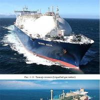 Basic tactical and technical characteristics
 Ria's rating Leader in terms of capitalization has changed again
 Top 10 most in-demand professions
 The largest farmland is in the hands of agro-oligarchs
 What kind of advertising was in the USSR The first advertising on television in the USSR