upon additional request and for an additional fee
Manufacturers of tabletop drilling machine C-25:
- Novosibirsk Radio Technical School
- Kalyazin Engineering College. Training and production workshops
S-25 desktop boring machine. Purpose and scope
Desktop drilling machine "S-25" is a precision machine designed for drilling precise holes in small parts made of cast iron, steel, non-ferrous alloys and non-metallic materials in industrial enterprises, repair shops and household workshops.
S-25 machines allow you to perform the following operations:
- drilling
- countersinking
- deployment
- reaming
Main technical characteristics of the S-25 table-top drilling machine (Kalyazin Machine-Building College)
Serial production began in 1953.
- Maximum drilling diameter - Ø 5 mm
- Maximum drilling depth (spindle stroke) - 75 mm
- Distance from the spindle axis to the bed (overhang) - 185 mm
- Spindle speed limits per minute - (6 steps) 1600..8000 rpm
- Spindle end - AT 10 O'CLOCK
- Electric motor power: 400 W
- Machine weight: 128 kg
Spindle the S-25 machine receives three speeds of rotation from three-stage drive pulleys, which provides a choice of 3 cutting speeds - 1600, 2500, 4000 rpm at engine speed 1400 rpm... At engine speed 2800 rpm the spindle rotation speed is 3200, 5000, 8000 rpm.
End of the spindle of the C-25 machine- external shortened cone B10 (Morse taper KM1) in accordance with GOST 9953 (shortened tool cones) - shortened cone: D = 10.094 mm.
The shortened cone B10 corresponds to a three-jaw drilling chuck of the 4th standard size in accordance with GOST 8522 (Three-jaw drilling chucks) with a clamping range of 0.5 ÷ 4 mm.
An example of a conventional designation of a drilling 3-jaw chuck of the 4th standard size:
Cartridge 4-B10 GOST 8522-79
Short tool Morse taper
Tool taper - Morse taper is one of the most widely used tool mountings. Was proposed by Stephen A. Morse around 1864.
Morse taper is subdivided into eight sizes- from KM0 to KM7 (in English: MT0-MT7, in German: MK0-MK7).
Morse taper standards: GOST 25557 (Tool tapers. Main dimensions), ISO 296, DIN 228. Tapers made according to inch and metric standards are interchangeable in everything except the shank thread.
For many applications, the length of the Morse taper was found to be excessive... Therefore, a standard was introduced for nine standard sizes of shortened Morse tapers (B7, B10, B12, B16, B18, B22, B24, B32, B45), these dimensions are obtained by removing the thicker part of the taper. The number in the designation of the short cone is the diameter of the thickest part of the cone in mm.
Russian standard for shortened cones GOST 9953 Shortened tool cones.
Russian standard for drill chucks GOST 8522 Three-jaw boring chucks.
- B7- Morse taper KM0, D = 7.067 mm;
- B10- Morse taper KM1, D = 10.094 mm. Cartridge 4-B10(0.5 ÷ 4 mm);
- B12- Morse taper KM1, D = 12.065 mm. Cartridge 6-B12(0.5 ÷ 6 mm), Chuck 8-B12(1 ÷ 8 mm);
- B16- Morse taper KM2, D = 15.733 mm. Cartridge 10-B16(1 ÷ 10 mm), Chuck 13-B16(1 ÷ 13 mm);
- B18- Morse taper KM2, D = 17.780 mm. Cartridge 16-B18(3 ÷ 16 mm);
- B22- Morse taper KM3, D = 21.793 mm. Cartridge 20-B22(5 ÷ 20 mm);
- B24- Morse taper KM3, D = 23.825 mm;
- B32- Morse taper KM4, D = 31.267 mm;
- B45- Morse taper KM5, D = 44.399 mm.
Where D is the diameter of the cone in the main plane.
Desktop drilling machine C-25 is a precision machine designed for drilling precise holes from 0.5 mm to 4 mm.
Spindle rotation, assembled on ball bearings, is produced from an individual squirrel-cage motor with a 3-stage pulley, due to which the spindle can rotate at six different speeds ranging from 1600 to 8000 rpm with a two-speed electric motor 1400, 2800 rpm.
Starting the motor produced by means of a packet switch.
Spindle smooth operation thanks to lightweight, well-balanced, aluminum pulleys, endless flat belt, protected by a die-cast hood with an easily removable cover.
Belt tension carried out by moving the motor together with the bracket.
Top end of spindle unloaded from a pulley rotating on individual ball bearings mounted in the bushing of the machine bed. The lower end is provided with a tapered hole for inserting a collet and a thread for a clamping nut.
Drill head includes the entire drive with drill spindle and feed unit. It is set at a height corresponding to the size of the product by means of a screw and nut and is clamped on the column using a handle.
The setting of the disc ring occurs in such a way that when the desired depth is reached, the ring receives a stop and stops the rotation of the roller with the gear.
Spindle feed- manual, made by means of a sensitive lever, gear and spindle glass.
The drilling spindle together with the bushing is balanced, located in the flange, adjustable by a flat spring, which is in communication with the gear and the lever. To set the spindle to a certain depth of drilling, a special clamp sitting on the gear shaft is used; a stop screw on the bed serves as a limiter for it.
Drilling table is a rectangular slab with stiffening ribs and at the same time is the base of the column. The table has a wide coolant drain groove and two T-slots for attaching accessories.
Column of the machine can be moved along the T-slot, thereby maintaining a large support surface for drilling large products with holes lying on the side.
Replacing a normal table with a large one makes it possible to install several columns side by side, and the distance between the individual columns can be adjusted as desired.

Photo of drilling machine S-25

Photo of drilling machine S-25

Photo of drilling machine S-25
С-25 Kinematic diagram of the drilling machine

Kinematic diagram of the C-25 drilling machine
Location of the components of the drilling machine C-25

- Column desk
- Spindle drive
- Electric motor
- Drilling head (headstock) with a spindle feed unit and a unit for moving the head along the column

Arrangement of controls for drilling machine s-25
- Handle for vertical movement of the spindle
- Handle for clamping the drill head on the column
- Handwheel for moving the drill head along the column
- Electric motor speed switch
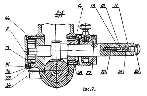
Drilling machine spindle feed unit s-25

Spindle assembly of drilling machine s-25

Electrical diagram of the drilling machine s-25
Installation of drilling machine S-25
The machine is installed on the table. Before tightening the bolts, the machine must be precisely aligned, for which a level is placed on the table up and down. After alignment, the bolts must be tightened securely while observing the level.
Machine start
Before starting, the machine must be thoroughly cleaned, rinsed with kerosene, wiped and lubricated, paying particular attention to rubbing surfaces and lubrication holes. After making sure of the correct installation and assembly of the machine, checking the rotation and movement of units and mechanisms in any direction, the machine starts up for a while, at idle, during which the operation of individual mechanisms is checked.
After carrying out the above operations, if nothing is in doubt, the machine is given a load.
Machine adjustment
The clamping of the spindle glass in the bed, the movement of the motor for tensioning the belt, the installation of the drilling head along the height of the workpiece and at a given drilling depth are subject to adjustment.
Control
The machine is switched on and off by starting and stopping the motor using a packet switch.
The speed is changed by transferring the belt from one stage of the pulleys to another with the motor turned off and the casing cover removed, guided by the speed table placed on the casing of the machine.
Machine lubrication
The most important parts to be lubricated are the spindle and the spindle cup, which during the operation of the machine are lubricated once a decade by pouring spindle oil No. 2 into the nipples.
The change of technical vaseline in the ball bearings of the spindle and spindle pulley is carried out once every 3 months.
Technical characteristics of the S-25 machine
- S-25 (1) - Novosibirsk radio technical school
- S-25 (2) - Kalyazin Mechanical Engineering College
| Parameter name | S-25 (1) | S-25 (2) |
|---|---|---|
| The main parameters of the machine | ||
| The largest conditional drilling diameter, mm | 6 | 1..5 |
| The smallest and largest distance from the end of the spindle to the table | 0..200 | 0..270 |
| Distance from the axis of the vertical spindle to the rack guides (overhang), mm | 125 | 185 |
| Desktop | ||
| Table working surface dimensions, mm | 220 x 300 | 180 x 500 |
| Number of T-slots Dimensions of T-slots | - | - |
| Spindle | ||
| The greatest movement of the spindle head along the column, mm | 210 | |
| Spindle sleeve stroke, mm | 70 | 75 |
| Spindle speed, rpm | 1600, 2500, 4000 3200, 5000, 8000 |
1600, 2500, 4000 3200, 5000, 8000 |
| Number of spindle speeds | 6 | 6 |
| Spindle taper | B10 (1a) | B10 (1) |
| Drive unit | ||
| Drive electric motor, kW (rpm) | 0,6 (1400, 2800) | 0,4 (1400, 2800) |
| Electric motor type | A031-4 / 2 | AOL 21-2 |
| Dimensions and weight of the machine | ||
| Machine dimensions (length width height), mm | 590 x 400 x 560 | 590 x 450 x 560 |
| Machine weight, kg | 80,5 | 128 |
Four-sided machine S25-4A is intended for the production of high-quality molded products (lining, floorboards, planed beams, platbands, plinths) from edged boards or beams in industrial volumes (up to 2 cubic meters / hour).
Workpieces are processed simultaneously from 4 sides with constant mechanical feed. The design and power of the machine allows you to process workpieces in a wide range of sizes. The machine bed is cast iron, box-shaped. The bed has four supports, a drive and a feed mechanism with pressure rollers.
Steel overhead tables and ruler guides with side clamps are attached to the upper plane of the bed. The feed drive, consisting of an electric motor and a variator, allows you to smoothly change the feed speed from 10 to 47 m / min. The spindles of the machine are designed with increased rigidity using special high-speed bearing assemblies.
Distinctive features C25-4A:
Lower drive hazelnut.
High productivity of the machine.
Exceptionally precise design of 4 high-speed spindle units.
High precision cast iron machine bed.
The feed rollers are located along the entire length of the workpiece.
The large base of the machine provides excellent geometric dimensions of the product.
The infinitely variable feed drive allows you to smoothly change the speed of movement of the workpiece.
High feed rate of the workpiece.
Convenient setting and changeover of the machine.
Technical characteristics of C25-4A:
|
Workpiece dimensions, mm: |
|
|
length not less |
|
|
Number of calipers, pcs |
|
|
Spindle speed, rpm |
|
|
Largest diameter of cutters (side), mm |
|
|
Feeding speed, m / min |
|
|
Number of electric motors, pcs |
|
|
Total power, kW |
|
|
Dimension, mm |
3460x1510x1870 |
|
Weight, kg |
Position 3441:
Year of issue: 1996.
Country of origin: Russia.
Location: Tver region.
Price on request.
Position 6423:
Year of issue: 1992.
Condition: very good, working.
Country of origin: Russia.
Location: Kostroma region.
Price on request.


Position 6891:
Condition: in good working order.
Country of origin: Russia.
Location: Republic of Karelia.
Price on request.
Position 8913:
Year of issue: 1990.
Condition: in good condition.
Country of origin: Russia.
Location: Nizhny Novgorod region
Price on request.
Four-sided machines of the C25-4AB series are designed for the production of various molded products and profiled timber, including natural moisture.
Distinctive features and equipment
- a heavy cast bed, which has undergone special processing, dampens any vibrations that occur during processing, allows you to get high-quality products;
- high-speed spindles of increased accuracy;
- for the manufacture of serving tables, Art. 40X (with chrome) for increased durability;
- distributed type feeder with top and bottom feed rollers;
- the pulley on the shaft of the modules moves freely, which allows you to get 4 constant gears. In combination with a frequency converter installed in the electrical cabinet and changing the rotation speed of the electric motor, the resulting speed range is from 2 to 40 m / min with guaranteed broaching of any workpieces;
- the upper feeding rollers are equipped with mechanical clamps, which allows processing at low negative temperatures;
- the feeding upper rollers can be equipped with a pneumatic clamping system with a stepless pressure force control, which can adjust the pressure separately;
- the upper feed rollers are made with wolf's tooth corrugation, which ensures the processing of workpieces of any moisture content, with less pressing of the rollers into the wood;
- the table lubrication system is used to reduce the load on the feed mechanism and to pull lumber of natural moisture;
- the machines are equipped with a digital display system for the movement of the spindles.
The processed lumber meets the following parameters
- the straightness of the base side of the processed workpiece is no more than 0.3 mm over a length of 1000 mm;
- the perpendicularity of the sides of the base face of the processed workpiece is no more than 0.25 mm over a length of 100 mm;
- uniformity of thickness and width of the processed sample no more than 0.3 mm.
Design features
| The cast bed, made of high-strength cast iron, provides exceptional rigidity and reliability of the machine, minimizes vibrations. | |
 |
The long front infeed table improves the quality and accuracy of the workpieces being cut. |
 |
The electrical cabinet and control panel are equipped with modern equipment. |
 |
Front clamps (sectional type) and rear clamps are adjustable to the size of processing, completely eliminate "breaks" at the entry and exit of the workpiece. |
 |
For processing workpieces with high humidity, the upper feed rollers are made with "wolf's tooth" corrugation |
 |
The task of facilitating the passage of the workpiece to be processed through the cutting zones and removing resin, dust from the surface of the tables is solved by the lubrication system. |
 |
The spindle positioning system is mounted on the front of the machine. For the convenience of operation, the mechanisms are equipped with digital indicators with an accuracy of 0.1 mm, which facilitates adjustment and control. |
 |
The change in the feed rate is stepless, provided by the variator. This guarantees a smooth and constant feed of the workpieces during machining. The torque is transmitted to the lower feed rollers via cardan shafts. |
Basic complete set of the machine
| Designation | Name | Quantity |
| S25-4AB.00.000 | Complete machine | 1 |
| S16-1A.00.028 | Sleeve (possibility of processing narrow workpieces). Installation instead of the left row of feed toothed rollers in the direction of travel of the workpiece | 8 |
| S25-5A.10.011-01 | Video clip. Replaces the toothed feed rollers for narrow workpieces. | 1 |
| IP.16.000 | Key. Tightening and loosening the nut to fix the tool on the spindle. | 1 |
| IP.17.000 | Key. Tightening and loosening the nut to fix the tool on the spindle. Ease of work with the right vertical support. | 1 |
| IP 35.000 | Ring set. Spacers for spindle shafts for the possibility of installing wood cutting tools of various lengths. | 4 |
| DIN468-160-V17 | Lever. Moving the calipers horizontally and vertically. Loosen and tighten the locking screws. | 1 |
| Key 7812-1606 D Chem. Oaks. prm. GOST 25787-83 | 1 | |
| Anti-noise headphones SOM 3 GOST 12.4.051-87. Delivery is carried out during the manufacture of the machine without ZIO, replacement with 14353M is allowed | 1 | |
| S25-4A.12.500 | Additional support (processing workpieces with a width of more than 160 mm with the lower horizontal spindle) | 1 |
| S25-4A.15.500-02 | Additional support. Processing workpieces over 160 mm with the upper horizontal spindle. | 1 |
| S25-4AB RE | Manual | 1 |
Replacement parts and accessories ordered as options
upon additional request and for an additional fee
| Soundproof fencing | Protection of personnel from noise vibrations. | 1 |
| Wooden box packing | 1 | |
| Electric motors 15 kW | Possibility to install electric motors of increased power on 2,3 spindles | set |
| Vibration mount | Installation on a foundation | 6 |
| S25-4AB.70.000 | Pneumatic clamping system. Simplifies the adjustment of the pressure force of the pinch rollers. | set |
| Electric motors 7.5 kW | Installation of electric motors of reduced power on any of the supports is possible. | set |
| IP.07.000 | Collet mandrel right. Possibility of installing a wood-cutting tool with a landing diameter of 60 mm on the upper horizontal spindle. | 1 |
| IP.07.000-02 | Collet mandrel right. Possibility of installing a wood-cutting tool with a landing diameter of 60 mm on the right vertical spindle. | 1 |
| IP.08.000-02 | Collet mandrel left. Possibility to install a wood-cutting tool with a landing diameter of 60 mm on the left vertical spindle | 1 |
| IP.23.000-02 | Tool for installing knives for prefabricated cutters. Installation of knives in wood-cutting cylindrical planing drums with a diameter of 140 mm | 1 |
| Bolt 1.1.М20Х330. St3 GOST 24379.1-80 | Foundation bolt. If vibration dampers are not purchased | 6 |
| The range and quantity of wood-cutting tools supplied with the machine is determined according to the supply agreement (including cylindrical cutters). | ||
The machine complies with the current GOST and TU for this group of goods, which is confirmed by the presence of a certificate of conformity and marks of the manufacturer's plant.
The supplied equipment is guaranteed for 12 months from the date of commissioning.
Feed drive
The workpiece feeding mechanism is driven by an electric motor (1).
The feed drive from the electric motor to the modules shaft is organized by a pulley (2) on the electric motor shaft and a pulley (3) on the splined shaft (4) of the modules (5). Pulleys 2-stage, 3-strand using the widespread V-belts A-1000 III GOST 1284.1-88 (6).
The pulley on the splined shaft of the modules moves freely, which allows you to get 4 constant gears. In combination with a frequency converter installed in the electrical cabinet of the machine and changing the rotation speed of the electric motor, the resulting total speed range is from 2 to 40 m / min. Tensioning, loosening or rearranging the belts is done by removing the guard (7) and turning the threaded screw (8).
1st gear.  |
2nd gear.  |
3rd gear.  |
4th gear.  |
Country of manufacture: Russia
S25-4AB. Four milling spindles of the heavy-duty machine.
The heavy machine series C25-4AB is designed for the production of various molded products and profiled timber, including natural moisture.
Features of 4-sided 4-spindle machine С25-4AB- The heavy cast bed, which has undergone special processing, dampens any vibrations that occur during the processing, and allows you to get high-quality products.
- High-speed spindles with increased precision.
- For the manufacture of feeding tables, 40X steel (with chrome) is used to increase wear resistance.
- Distributed type feeder with top and bottom feed rollers.
- The drive for feeding from the electric motor to the modules shaft is organized by a pulley on the electric motor shaft and a pulley on the modules shaft. Pulleys 2-stage, 3-strand using common V-belts. The pulley on the shaft of the modules moves freely, which allows you to get 4 constant gears. In combination with a frequency converter installed in an electrical cabinet and changing the rotation speed of the electric motor, the resulting speed range is from 2 to 40 m / min with guaranteed broaching of any workpieces.
- The upper feed rollers are equipped with mechanical clamps, which allows processing at low negative temperatures.
- The top feed rolls can be equipped with a pneumatic pressure system with stepless pressure force control, which can adjust the pressure separately.
- The upper feed rollers are made with "wolf's tooth" corrugation, which ensures the processing of a workpiece of any moisture content, with less pressing of the rollers into the wood.
- The table lubrication system is used to reduce the load on the feed mechanism and to pull the lumber of natural moisture.
- The machines are equipped with a digital display system for the movement of the spindles.
- The aspiration system is purchased at the rate of 2000 m 3 / h for one machine support.
- The machine complies with the current GOST and TU for this group of goods, which is confirmed by the presence of a certificate of conformity and marks of the manufacturer's plant.
- The supplied equipment is guaranteed for 12 months from the date of commissioning by the manufacturer or a representative of the plant (dealer).
- The straightness of the base side of the processed workpiece is no more than 0.3 mm over a length of 1000 mm.
- The perpendicularity of the sides of the base face of the processed workpiece is no more than 0.25 mm over a length of 100 mm.
- The uniformity of the thickness and width of the processed sample is no more than 0.3 mm.
Replacement parts and accessories *, ordered as an option (upon additional request and at an additional cost). You can check the exact price and production time from our managers.
* - the range and quantity of wood-cutting tools supplied with the machine is determined according to the supply agreement (including cylindrical cutters).
We recommend purchasing additionally- Soundproof fence. Personnel protection from noise vibrations - 1 pc.
- Electric motors of 2,3 spindles, 15 kW each. Installation of high-power electric motors on vertical supports - 1 set.
- Electric motors 7.5 kW. It is possible to install low-power electric motors on any of the supports - 1 set.
- Packing wooden box - 1 pc.
- Vibration mount. Foundation installations - 6 pcs.
- Pneumatic clamping system. Simplifies the adjustment of the pressure force of the pinch rollers. (С25-4АБ.70.000) - 1 set
- Collet mandrel right. Possibility of installing a wood-cutting tool with a landing diameter of 60 mm on the upper horizontal spindle. (IP.07.000) - 1 pc.
- Collet mandrel right. Possibility of installing a wood-cutting tool with a landing diameter of 60 mm on the right vertical spindle. (IP.07.000-02) - 1 pc.
- Collet mandrel left. Possibility of installing a wood-cutting tool with a landing diameter of 60 mm on the left vertical spindle. (IP.08.000-02) - 1 pc.
- Tool for removing cutters. Removing cylindrical wood cutters from spindle shafts. (IP.12.000) - 1 pc.
- Tool for installing knives for prefabricated cutters. Installation of knives in wood-cutting cylindrical planing drums with a diameter of 140 mm. (IP.23.000-02) - 1 pc.
- Foundation bolt. If vibration mounts are not purchased. (1.1.M20X330. St3 GOST 24379.1-80) - 6 pcs.
| Specifications | S25-4AB |
| Workpiece dimensions, mm | |
| Processing width with horizontal milling cutters with a diameter of 140 mm | 35-260 |
| Height of processing with vertical milling cutters 140 mm | 12-230 |
| Minimum workpiece length when processing in a stream | 250 |
| Minimum length of a single piece | 700 |
| Minimum product dimensions, mm | |
| Width with cutters 140 mm | 30 |
| Height with cutters 140 mm | 10 |
| Maximum allowance for processing with cylindrical cutters, mm | |
| On the 1st spindle | 8 |
| On 2-4 spindles | 10 |
| Number of spindles, pcs | 4 |
| Spindle speed, rpm | 6000 |
| Profiling depth, mm | |
| On the 1st spindle | 3 |
| On 2-4 spindles | 30 |
| Landing dimensions of horizontal spindles, mm | |
| Length | 260 |
| Diameter | 50 |
| Landing dimensions of vertical spindles, mm | |
| Length | 230 |
| Diameter | 50 |
| Diameter of cylindrical cutters, mm | 125-140 |
| * Diameter of vertical profile cutters, mm | 110-200 |
| Horizontal profile cutter diameter, mm | 110-200 |
| Feeding speed, m / min | 2-40 |
| power, kWt | |
| 1st spindle motor | 11 |
| 2nd spindle motor | 11 |
| 3rd spindle motor | 11 |
| 4th spindle motor | 11 |
| Feed drive | 4 |
| Lifting-lowering | 1,1 |
| Total machine power (rounded off), kW | 50 |
| Diameter of outlet branch pipes of aspiration, mm | DN150 |
| Required aspiration capacity, m 3 / h | 4x2000 |
| Overall dimensions of the machine, mm | |
| Length | 4300 |
| Width | 1500 |
| Height | 2000 |
| Weight, kg | |
| Machine tool | 4600 |
* - profile cutters are not installed on the lower support.
Delivery set of the four-sided machine C25-4AB- Assembled machine. (С25-4АБ.00.000) - 1 pc.
- Sleeve (possibility of processing narrow workpieces). Installation instead of the left row of feed toothed rollers in the direction of travel of the workpiece. (С16-1А.00.028) - 8 pcs.
- Key. Tightening and loosening the nut to fix the tool on the spindle. (IP.16.000) - 1 pc.
- Key. Tightening and loosening the nut to fix the tool on the spindle. Ease of work with the right vertical support. (IP.17.000) - 1 pc.
- Ring set. Spacers for horizontal spindle shafts to accommodate wood cutting tools of various lengths. (IP 35.000) - 4 pcs.
- Lever. Moving the calipers horizontally and vertically. Loosen and tighten the locking screws. (DIN468-160-V17) - 1 pc.
- Key. (7812-1606 D Chem. Ox. Prm. GOST 25787-83) - 1 pc.
- Anti-noise headphones. (СОМ 3 GOST 12.4.051-87) - 1 pc.
- Additional support. Processing workpieces with a width of more than 160 mm with the lower horizontal spindle. (С25-4А.12.500) - 1 pc.
- Additional support. Processing workpieces over 160 mm with the upper horizontal spindle. (С25-4А.15.500-02) - 1 pc.
- Manual. (S25-4AB RE) - 1 pc.
The workpiece feeding mechanism is driven by an electric motor (1). The feed drive from the electric motor to the modules shaft is organized by a pulley (2) on the electric motor shaft and a pulley (3) on the splined shaft (4) of the modules (5). Pulleys 2-step, 3-groove using the widespread V-belts A-1000 III GOST 1284.1-88 (6). The pulley on the splined shaft of the modules moves freely, which allows you to get 4 constant gears. In combination with a frequency converter installed in the electrical cabinet of the machine and changing the rotation speed of the electric motor, the resulting total speed range is from 2 to 40 m / min. Tensioning, loosening or rearranging the belts is done by removing the guard (7) and turning the threaded screw (8).
Feed speed 7 m / min at 50 Hz (with frequency converter 2-14 m / min).

Feed speed 10 m / min at 50 Hz (with frequency converter 5-20 m / min).

Feed speed 13 m / min at 50 Hz (with frequency converter 6-26 m / min).

Feed speed 19 m / min at 50 Hz (with frequency converter 9-40 m / min).
 From a student of a FZU school to a director and a minister (Hero of Socialist Labor V
 Law on public organizations of the Russian Federation
 Votkinsk machine-building plant: history, products, address Votkinsk machine-building plant
 Founder's decision to appoint a director of sample ltd
 Sample notification of the start of business
 What is a journal-order accounting system in accounting
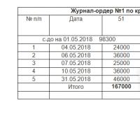 Journal-order: sample filling