Camera viewing angle with a lens 1.2.8. Dependence of the angle of view on the focal length of the camera lens. Object distance
The most important parameter of a video surveillance camera (even more important than resolution and sensitivity) is the viewing angle or focal length of the lens. It depends on this parameter whether you can distinguish or identify a person at a certain distance. And it is very important to find the right compromise between the wide angle of view of the camcorder and the necessary image detail.
Beginners often make the mistake of thinking that if you put a camera with a high resolution, then even with a wide viewing angle, it will be possible to recognize a person at a sufficient distance. However, it is not. Here's one helpful tip for getting the right focal length:
1. A familiar person, in the field of view of a video camera, can be recognized at a distance no more than the focal length of the camera lens in meters. For example, a video camera with f = 9 mm. will allow you to recognize a person at a distance of up to 9 m.
2. A stranger in the field of view of a video camera can be 100% identified at a distance of no more than half the focal length of a video camera lens in meters. For example, a video camera with f = 9 mm. will allow you to identify a person at a distance of up to 4.5 m.
An example of an image from a video camera with different focal lengths (angle of view)


The following tables show the horizontal and vertical viewing angles of video cameras depending on the size of the sensors and the focal length of the lens.
|
Matrix format 1/4 " |
Matrix format 1/3 " |
|||||||||||||||||||||||||||||||||||||||||||||||||||||||||||||||||||||||||||||||||||||||||||||||||||||||||||||||||||||||||||||||||||||||||||||||||||||||||||||||||||||||||||
|
|
|||||||||||||||||||||||||||||||||||||||||||||||||||||||||||||||||||||||||||||||||||||||||||||||||||||||||||||||||||||||||||||||||||||||||||||||||||||||||||||||||||||||||||
|
Matrix format 1 / 2.8 " |
Matrix format 1 / 2.5 " |
||||||||||||||||||||||||||||||||||||||||||||||||||||||||||||||||||||||||||||||||||||||||||||||||||||||||||||||||||||||||||||||||||||||||||||||||||||||||||||||||||||||||||||
|
|
||||||||||||||||||||||||||||||||||||||||||||||||||||||||||||||||||||||||||||||||||||||||||||||||||||||||||||||||||||||||||||||||||||||||||||||||||||||||||||||||||||||||||||
Many people overlook the fact that the size of the sensor plays no less role in the formation of the camera's angle of view than the lens. It is interesting to note that on a camcorder with a cheap 1/4 matrix and 2.8 lens, the viewing angle will be smaller than the standard 1/3 sensor and standard lens 3.6 - 59 ° versus 67 ° horizontally!
More and more often, our clients are asking for CCTV cameras with a viewing angle of 120 degrees or more. Most people who are not familiar with this topic are sure that this is a typical value for standard video cameras. To be honest, many of the retailers also claim that cameras with a 2.8mm lens have a 120 ° horizontal field of view. Let's take a look at the real values. We have already measured and debunked the myth that most of them have a viewing angle of 120 degrees or more.
When choosing equipment for a security surveillance system, of course, it is important to take into account the viewing angle of CCTV cameras, on which the size of the observed area depends. Its value is influenced by 2 parameters - the focal length of the lens and the diagonal of the matrix, with an increase in which the angle of view will expand. But with an increase in the angle of the field of view, the image detail decreases. For more detail, you need a higher resolution or a camera with a narrower angle of view.
For a visual comparison of the angles of the field of view on cameras with different lenses, an experiment was carried out, which is described later in the article.
We used 3 IP cameras with different lenses:
- 3.6mm -
- 2.8mm -
- 1.9mm -
The tested camcorders differ in the focal length of the lens. Cameras with 3.6 and 1.9mm lenses have the same matrix size of 1 / 2.9 ", a camera with 2.8 lens has a slightly larger matrix - 1 / 2.7". And the resolution of all cameras is 2 megapixels.
All video cameras were placed at a height of about 2 meters opposite the "test" wall in our office. The camera views were aligned to the center to better assess the difference in the width of the field of view. One shot was taken for each of the following three cameras:
Angle of view of a camcorder with a 3.6mm lens:
With a focal length of 3.6 mm. The two outermost armchairs of the managers and part of the right wall are visible. The field of view is approximately 73 °.
Video camera viewing angle with 2.8mm lens:

With a focal length of 2.8 mm. Now in the frame you can see about 2 m more - the part of the right showcase and the window on the left. With this camcorder, the viewing angle has increased to 89 °.
Video camera viewing angle with 1.9mm lens:

With a focal length of 1.9 mm. The screenshot shows that both showcases and even part of the doorway of the trading floor are already in the frame of this camera. Its viewing angle reaches 109 °.
It can be more clearly represented in this way:

Camcorders with a small field of view have a higher pixel density, which means better image detail. Such a viewing width will be enough for many, so such cameras remain popular in video surveillance. If you need to capture a larger area for observation, you will need a camera with a wider viewing angle.
Calculation of viewing angles of CCTV cameras for all 3 cases
a = 2arctg (d / 2f),
a - angle of view of the video camera, in metric degrees;
arctg - trigonometric function (arctangent);
d is the width of the matrix in millimeters;
f is the effective focal length of the lens in millimeters;
For 3.6mm, PN-IP2-B3.6 v. 2.6.3
a1 = 2 * arctan (5.376mm / 2 * 3.6) = 73 degrees
For 2.8mm, ST-181 HOME 2.8
a2 = 2 * arctan (5.47mm / 2 * 2.8) = 89 degrees
For 1.9mm, PNL-IP2-B1.9MPA v.5.5.2
a3 = 2 * arctan (5.376mm / 2 * 1.9) = 109 degrees
In tabular form, it will look like this:
|
Lens |
||
Basic information:
As you know, LCD displays have a limited viewing angle. The contrast of the image is highly dependent on the angle of incidence of the view on the LCD panel. At certain angles, the contrast reaches a maximum, and the image is easy to read, at other angles, the contrast drops sharply and reading information from the screen is very difficult. The physical dimensions of the permissible viewing angle, hereinafter referred to as the viewing angle, are determined by several factors, the main of which are the type of “liquid crystals” and power cycles. Since the viewing angle is generally less than desired, each LCD module acquires a viewing direction reference during its manufacture. Most often, the optimal viewing angle is shifted relative to the normal to the module surface.
Several types of LCD modules are offered by manufacturers with reference directions set at different angles or positions to cover as many different module applications as possible. The term reference direction or offset angle is often confused with viewing angle.
Defining "offset angle" and "viewing angle"
Offset angle is the angle between the normal to the LCD surface and the direction from which the display provides the best image and maximum contrast, see Figure 1.
This angle is determined by the design of the display and can be set during production in any direction or orientation. The orientation of the offset angle of the displays is often formulated using the reference directions of the dial of the analogue clock. If the direction of the best view is above the display, talk about a 12:00 offset or a major offset. Hantronix offers standard LCD displays in both 12:00 and 6:00 offset positions, as well as custom modules with any offset angles.
Fig. 1 Viewing angle
The viewing angle is the angle formed on both sides of the offset angle within which the display contrast remains high enough. Hantronix limits this contrast reduction within the viewing angle to a ratio of 1.4: 1. STN digital display with 1/16 cycle has a viewing angle within 20 degrees and an offset angle of 25 degrees. When this display is viewed at an angle of 25 degrees above the normal (as shown in Figure 1) it has the maximum contrast and the best image. In this example, the display is offset at 12:00, i.e. displacement of the main type. When the observer's eyes are shifted relative to the display by an additional angle within 30 degrees, the contrast of the display decreases, but the image remains sufficiently clear and easy to read. A further increase in this angle leads to a significant decrease in image quality.
Contrast adjustment and its effect on the viewing angle
Adjusting the contrast voltage, VL, sets the offset angle to a specific position, but does not affect the viewing angle. A display with an offset angle of 12:00 can be optimized for an angle of 6:00 by adjusting the contrast voltage. But the 12:00 o'clock display set to the 6:00 position of the offset angle will not have the same high contrast as the 6:00 o'clock at the 6:00 position and vice versa.
Designers often wish to have LCD displays optimized for zero offset angle, where contrast is maximized when the viewer's eye falls normally on the panel.
Both 12:00 and 6:00 module types can be used for this purpose, and the contrast voltage is simply adjusted to optimize displays at a given viewing angle.
For example, in the previous displays, the viewing angle of both types of displays and 12:00 and 6:00 overlaps the perpendicular to the surface of the displays.
Contrast adjustment procedure
Once set, the offset angle of the display in accordance with its design, however, can be adjusted later in accordance with its application. This is confirmed by the results of the development of many prototypes of products with LCD displays. For such adjustment, a potentiometer with a resistance of about 10 kΩ is required, connected to the power supply rails of the module, as shown in Fig. 2, for two power supply options, one and two-pole.
In this case, the potentiometer slider is connected to the VL input of the module. The LCD is set to the position where it is seen at the desired offset angle. By adjusting the position of the potentiometer slider, and with it the VL voltage, the optimal image contrast is achieved. In this case, the VL voltage can be measured and recorded.
Subsequently, the potentiometer can be replaced in the product with a divider of two resistors, which generates the required voltage VL.

Fig. 2.
Selecting the required module for the product
Most of the manufactured electronic products, during operation, have a certain spatial position. For desk-mounted devices such as calculators, the displays are mostly seen from the top. This is usually the case for small measuring instruments as well. For these applications, 6:00 LCD modules should be preferred. for products where the LCD module is located vertically, for example, on the dashboard of a car or airplane, preference should be given to 12:00 modules.
Conclusion
The choice of LCD displays is very important in terms of viewing angle, however, the designer should keep in mind that the contrast setting is equally important, since both of these parameters together affect the image quality of the selected module, and ultimately the attractiveness of your design.
Original file:
| 45 Kb Engl 3224app.pdf |
A video camera is a mechanical device consisting of a body, a lens and an electronic converter of an optical image into an electronic form of signals:
- Frame- the main power element designed for fastening various parts of one product.
- Lens- an optical element consisting of one or more lenses with different diopters. Responsible for creating a virtual or real image in an enlarged or reduced form.
- Electronic converter, or, in other words, CCD-matrix- an integrated microcircuit consisting of photodiodes that convert a light signal (image) into a set of electrical signals for the purpose of their further transmission to a receiver (monitor).
Main characteristics
Any optical-mechanical device, including a surveillance camera, has a number of important characteristics that determine the effectiveness of their work:
- focus and sensitivity of the lens;
- resolution;
- CCD matrix format;
- the possibility of digital signal processing;
- angle of view of the video camera;
All these characteristics are closely interconnected and determine, in fact, the power of the optical instrument.
Let's consider one of the most important indicators - the viewing angle of a video camera. To make it clearer what it is, you can draw an analogy with a human optical instrument, the eye is the angle of view, the coverage of the maximum visible space.
Viewing angle

The viewing angle characterizes the apparent girth of the observed space. Directly depends on the focal length of the lens and the size of the CCD-matrix. So, with the same lenses, the angle of view will be larger for a camcorder with a larger matrix.
The viewing angle is an important parameter for a surveillance camera. The larger it is, the wider the observation area. It follows that with a greater coverage of observation by one camera, less of them will be needed to control a certain area. To determine the number of observation devices, it is necessary to calculate the viewing angle.
Payment

The calculation can be performed using several methods.
The angle of view directly depends on the focal length. It follows that, having calculated the latter, using the above table 1, you can determine the desired angle.
The calculation formula looks like this: f = r * A / L, where:
- f is the focal length of the lens.
- r is the metric distance to the object, measured in meters.
- A is the size in millimeters of one of the sides of the matrix; the one that defines the observation plane is accepted: vertical or horizontal observation area.
- L - object dimensions in meters; taken in accordance with the dimensional side of the matrix: vertically or horizontally.
Thus, the viewing angle will be calculated at which the object will occupy almost the entire monitor screen. Taking into account the importance of the object and the expediency of observing the territory located around it, it is determined in% that part of the screen, which the protected object can occupy.
In this case, the final formula takes the form: f = r * A / (100 * L / h), where:
- h - full size of the object on the screen, expressed as a percentage;
Manual calculations using this technique are quite time consuming, therefore, appropriate programs for computer calculations have been developed.
Calculation example:
The object of observation is the entrance gate to the territory of the enterprise. The task facing the surveillance service is to record the marks and license plates of entering and leaving vehicles.
Initial data for the calculation:
- r = 10 meters, - distance from the lens to the border of the gate;
- h = 5%, - horizontal size of the object on the monitor;
- A = 8.46 mm (1/3 "), is the size of the matrix;
- L = 0.52 meters, - the size of the license plate;
Then the focal length of the lens will be: f = 10 * 8.46 / (100 * 0.52 / 5) = 10.429 mm.
Checking the table, we see that the camera's angle of view will be about 27 degrees.
The viewing angle can be determined in a shorter way, but it should be taken into account that inexpensive lenses suffer from optical distortion, especially strong spherical aberration.
Calculation formula: a = 2arctg (b / 2f), where:
- a - angle of view of the video camera, in metric degrees;
- trigonometric function (arctangent);
- b is the size of the matrix in millimeters on one of the sides;
- f is the effective focal length of the lens in millimeters;
Calculation example:
The object of observation is exactly the same as in the above example. We accept the initial data exactly the same.
The viewing angle will be: a = 2arctg (8.46 / 2 * 10.5) = 29 degrees.
The discrepancy between the results is caused by a slight rounding of the original data to the second decimal place.
Modern short throw lenses can achieve an angle of view in excess of 180 degrees (door peepholes), but this raises another problem. Linear outlines of objects are strongly distorted by spherical aberration - the image takes on a curved shape. Hence the conclusion: the longer the focal length, the clearer the object is seen, but at a smaller viewing angle.
Image clarity
The clarity of the image, or the resolution of surveillance cameras- this is the ability of the device to confidently record the minimum size of the object of observation at a certain distance to the camera.
Resolution, and accordingly, the clarity of the image depends on:
- on the quality of the lens and its focal length;
- on the technical characteristics of the CCD matrix (the number and quality of pixels);
- from distance: "lens - observed object";
If a visual receiving device (monitor) is used, then the following are added:
- the quality of signal conversion in the receiving device (video recorder);
- technical characteristics of the reproducing device (monitor);
For different cameras - analog and IT-technologies (digital) clarity is determined by their characteristics.
Analog video cameras

For this type of cameras, the TVL indicator is used - television lines. Shows how many alternating black and white lines are placed on the measured area in the vertical or horizontal planes.
Analog cameras, according to the degree of resolution, are subdivided into devices:
- with medium image quality: about 500 pixels, - corresponds to 380 ... 420 TVL;
- high resolution: more than 750 pixels - more than 1000 TV lines, respectively;
In digital, IP-cameras, the sharpness index is determined by pixels, more precisely, the number obtained from multiplying the number of pixels vertically and horizontally, respectively. The accompanying instructions indicate this number, expressed in megapixels.
Many are familiar with this characteristic - this is how the properties of a video camera in a mobile phone are characterized.
Object distance

Figure 1 (at the beginning of the article) shows that objects "1" and "2", located at the same viewing angle, are displayed on the matrix in the same way, the number of pixels involved per perception of both objects is equal. In other words, the amount of information comes in different, but the closer located object has a smaller amount of data - its detailing is clearer, small details are not "smeared", do not merge with each other.
In order to increase the resolution and detail of the object, it is necessary to bring the object “2” closer to the lens. This is done by changing the focal length, that is, the camera "zooms in" to the object. But this is applicable only for camcorders with lenses with variable focal length ("floating" lens).
It is possible to equip the receiving device with special software that allows processing the received digital signal in order to increase the detail of the observed object. But this will lead to a significant increase in the cost of the video surveillance system.
Examples of the dependence of the clarity of the picture on the focal length of the lens, the angle of view and the distance to the object are given in the table:
| Lens focal length, mm | Horizontal angle of view for matrix = 1/3 ", linear degrees | The ability to detect a person, meters (approximate data) | The ability to identify a person, meters(approximate data) | The ability to determine the car number, meters(approximate data) |
| 2,8 | 86 | 19 | 1,4 | – |
| 3,6 | 72 | 25 | 1,8 | – |
| 4,0 | 67 | 28 | 2 | 5 |
| 8,0 | 36 | 56 | 4 | 5 |
| 12,0 | 25 | 84 | 6 | 8 |
| 25,0 | 12 | 175 | 12,5 | 16 |
| 50,0 | 6 | 350 | 25 | 33 |
| 80,0 | 3,3 | 560 | 40 | 53 |
| 120,0 | 2,1 | 840 | 60 | 80 |
Note: a person with normal vision covers about 34 ... 38 degrees in the horizontal plane. This corresponds to approximately 6.9 mm average focal length with a 1/3 ”sensor. Cameras with lenses less than 7mm (short throw) will optically remove the subject; with lenses over 7 mm (medium and long focal lengths), the object is visually brought closer.
When calculating distances, European standards are taken as a basis:
- 20 pixels / meter- norm for resolution when an object is detected in the field of view;
- 100 pixels / meter- an indicator used for object recognition;
- 250 pixels / meter- permission for identification;
The text contains the determining factors responsible for the angle of view of the camcorder.
But during operation, such factors arise that affect the performance of the device:
- disruption of the lens performance, in the case of the manufacture of the optical component from a polymer material (lens clouding);
- poor-quality fastening of the body to the supporting structure (tremor from gusts of wind or other influences);
- loss of its properties as a lubricating component in the construction of a video camera (the complexity of moving the camera itself or lens);
- electronic interference affecting the transmitted signal, as well as various other factors;
In addition to theoretical calculations for the viewing angle, important factors are:
- the installation point should provide maximum visibility in the vertical and horizontal planes;
- protection from the effects of climatic or any mechanical influences;
- availability, when performing preventive work on adjusting the video camera and preventive maintenance;
Each object requires an individual approach when determining the viewing angle, the clarity of the picture on the monitor. All this is determined when setting tasks to determine the parameters of the observed territory and is calculated by specialists.
When designing, it is important to take into account the features of the equipment used, which directly determine the efficiency and quality of video recording. In addition to the location and technical characteristics of surveillance cameras, one of the most important components is to determine the viewing angle, since the capture of the camera in width and height, as well as the range of visibility, depends on this parameter. For each camera, the choice of the viewing angle should be an individual parameter, since they are all located in different places with their own characteristics. For example, for a camera installed in a narrow corridor, the priority parameter will be a narrow capture with a long direction, while cameras located in a large room or in an open area should capture a wider part of the space.
There are types of cameras that are equipped with varifocal lenses, i.e. lenses that allow you to change the angle of view by changing the focal length, thereby adjusting the optimal grip and direction on site. Zoom cameras allow you to control the varifocal lens from the remote control, where you can immediately follow the changes on the screen.
When determining the viewing angle of a video camera, the main functions of the optical elements should be taken into account:
- Decreasing the focal length (F) increases the angle of view.
- Increasing the focal length, decreasing the visibility.
- The smaller the diagonal of the CCD matrix size, the smaller the viewing angle (with the same lenses).
In some cases, CCTV cameras can be equipped with lenses that have a viewing angle of 120 degrees or more in the horizontal plane (for example, video door peepholes, car DVR cameras, fisheye cameras, and others). The image obtained with such cameras lends itself to optical distortion and looks like a convex picture, blurred on the sides, in which it is very difficult to see small details and people's faces. As a rule, such cameras are used for general assessment of events at sites.
Video camera lenses use only discrete focal length values with a certain step, which equates to 10-15 degrees on the horizontal scale. As practice shows, such a step is enough to find the optimal ratio for the desired viewing angle. In cases where the specific conditions of the protected object require a very accurate definition of visibility, it is better to use vario-lenses with manual focal length adjustment or a zoom mechanism, which will allow you to select the optimal parameter. But, it should be borne in mind that the price of such lenses is much higher and the optical power is inferior to correctly selected fixed lenses with a fixed focal length.
Below are the values of visibility for various matrices, as well as approximate indicators of the distance of visibility and recognition of objects:
Values for camcorders with 1/4 inch matrixes
| Focal length, mm | |||||
|---|---|---|---|---|---|
| 2,5 | 51.28 | 65.24 | 77.32 | 3.12 | 1.25 |
| 2,9 | 44.96 | 57.77 | 69.18 | 3.62 | 1.45 |
| 3,4 | 38.88 | 50.40 | 60.93 | 4.25 | 1.70 |
| 3,5 | 37.85 | 49.13 | 59.49 | 4.37 | 1.75 |
| 3,6 | 36.87 | 47.92 | 58.11 | 4.50 | 1.80 |
| 3,7 | 35.94 | 46.77 | 56.79 | 4.62 | 1.85 |
| 4,0 | 33.40 | 43.60 | 53.13 | 5.00 | 2.00 |
| 4,3 | 31.19 | 40.82 | 49.89 | 5.37 | 2.15 |
| 5,5 | 34.62 | 32.44 | 39.97 | 6.87 | 2.75 |
| 6,0 | 29.86 | 36.87 | 7.50 | 3.00 | |
| 8,0 | 17.06 | 22.62 | 28.07 | 10.00 | 4.00 |
| 12,0 | 11.42 | 15.19 | 18.92 | 15.00 | 6.00 |
| 16,0 | 8.578 | 11.42 | 14.25 | 20.00 | 8.00 |
| 25,0 | 5.496 | 7.324 | 9.148 | 31.25 | 12.50 |
| 50,0 | 2.750 | 3.666 | 4.581 | 62.50 | 25.00 |
| 75,0 | 1.833 | 2.444 | 3.055 | 93.75 | 37.50 |
1/3 inch die
| Focal length, mm | Vertical viewing angle, degrees | Horizontal viewing angle, degrees | Diagonal viewing angle, degrees | Recognition distance, meter | Distance of the best quality |
|---|---|---|---|---|---|
| 2,5 | 71.50 | 87.66 | 100.38 | 2.08 | 0.83 |
| 2,9 | 63.65 | 79.22 | 91.94 | 2.41 | 0.96 |
| 3,4 | 55.79 | 70.43 | 82.84 | 2.83 | 1.13 |
| 3,5 | 54.43 | 68.87 | 81.20 | 2.91 | 1.66 |
| 3,6 | 53.13 | 67.38 | 79.61 | 3.00 | 1.20 |
| 3,7 | 51.88 | 65.93 | 78.07 | 3.08 | 1.23 |
| 4,0 | 48.45 | 61.92 | 73.73 | 3.33 | 1.33 |
| 4,3 | 45.42 | 58.33 | 69.80 | 3.58 | 1.43 |
| 5,5 | 36.24 | 47.14 | 57.22 | 4.58 | 1.83 |
| 6,0 | 43.60 | 53.13 | 5.00 | 2.00 | |
| 8,0 | 25.36 | 33.39 | 41.11 | 6.66 | 2.66 |
| 12,0 | 17.06 | 22.62 | 28.07 | 10.00 | 4.00 |
| 16,0 | 12.83 | 17.06 | 21.23 | 13.33 | 5.33 |
| 25,0 | 8.23 | 10.96 | 13.68 | 20.83 | 8.33 |
| 50,0 | 4.12 | 5.49 | 6.86 | 41.66 | 16.66 |
| 75,0 | 2,75 | 3.66 | 4,58 | 62.50 | 25.00 |
1/2 inch die
| Focal length, mm | Vertical viewing angle, degrees | Horizontal viewing angle, degrees | Diagonal viewing angle, degrees | Recognition distance, meter | Distance of the best quality |
|---|---|---|---|---|---|
| 2,5 | 87.66 | 104.00 | 115.98 | 1.56 | 0.52 |
| 2,9 | 79.22 | 95.63 | 108.11 | 1.81 | 0.72 |
| 3,4 | 70.43 | 86.52 | 99.27 | 2.12 | 0.85 |
| 3,5 | 68.87 | 84.87 | 97.62 | 2,18 | 0.87 |
| 3,6 | 67.38 | 83.26 | 96.02 | 2.25 | 0.90 |
| 3,7 | 65.93 | 81.71 | 94.46 | 2.31 | 0.92 |
| 4,0 | 61.92 | 77.31 | 90.00 | 2.50 | 1.00 |
| 4,3 | 58.33 | 73.31 | 85.85 | 2.68 | 1.07 |
| 5,5 | 47.14 | 60.38 | 72.05 | 3.43 | 1.37 |
| 6,0 | 43.60 | 56.14 | 67.38 | 3.75 | 1.50 |
| 8,0 | 33.39 | 43.60 | 53.13 | 5.00 | 2.00 |
| 12,0 | 22.61 | 29.86 | 36.86 | 7.50 | 3.00 |
| 16,0 | 17.06 | 22.61 | 28.07 | 10.00 | 4.00 |
| 25,0 | 10.96 | 14.58 | 18.18 | 15.62 | 6.25 |
| 50,0 | 5.49 | 7.32 | 9.14 | 31.25 | 12.50 |
| 75,0 | 4.88 | 6.10 | 46.87 | 18.75 |
These values are approximate, taking into account the location of the video camera at a height of 2.5 meters. The calculation of the exact values is made according to the formula:
F = C × D ÷ W
F is the focal length of the lens, mm.
C is the width of the CCD matrix, mm.
D is the distance from the video camera to the object, m.
W is the width of the observed object, m.
.jpg)
When determining the visibility, it is also necessary to take into account the feature of the reverse scanning of monitors, in which the image on the screen is displayed not completely, but with a deduction of 10% from the total of four boundaries.
The standard angle of view of television cameras is considered to be 30 degrees, regardless of the aspect ratio. This value became the standard because it corresponds to the optimal visual perception of perspective by the human eye.
Head of the technical support group Benedikt Maksimenko.
 Traffic rules, traffic lights, road signs
 Fairy-tale bird abstract of the lesson on visual activity with the use of elements
 Activity lesson in the preparatory group "magic firebird"
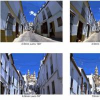 Camera angle of view with lens 1
 Types of printer paper
 How to connect to the Internet of a home computer via an ADSL modem
 What is OEM, Box and Kit?