Thread image. Unified system of design documentation. Thread image GOST 2.311 68 image
The construction of a helical surface in a drawing is a lengthy and complex process, therefore, in the drawings of products, the thread is depicted conditionally, in accordance with GOST 2.311–68. The helix is replaced by two lines - a solid main line and a solid thin line.
Threads are subdivided according to their location on the surface of the part into external and internal.
Conditional image threads on the rod.
Fig.7
The external thread on the rod (Fig. 7) is depicted by solid main lines along the outer diameter and solid thin lines along the inner diameter, and on images obtained by projecting onto a plane perpendicular to the axis of the rod, a thin line is drawn on 3/4 of the circle, and this line can be open anywhere (it is not allowed to start a solid thin line and end it on the center line). The distance between a thin line and a solid main line should not be less than 0.8 mm and more than the thread pitch, and the chamfer is not shown in this view. The thread boundary is applied at the end of the complete thread profile (before the start of the run) with a solid main line, if it is visible. The thread run, if necessary, is depicted as a solid thin line.

Fig.8
For technological reasons, thread undercutting can be carried out on a part of a part (rod). In total, the thread undercut and the run-out are the thread undercut (GOST 10548–80). The size of the thread length is indicated, as a rule, without a run.
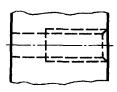
Symbolic image of a thread in a hole

Fig.9
Internal thread – is depicted as a solid main line along the inner diameter and a solid thin line along the outer one. If, when depicting a blind hole, the end of the thread is located close to its bottom, then it is allowed to depict the thread to the end of the hole. Threads with a non-standard profile should be depicted.
Conditional image of the thread assembly.

Fig.10
On sections of a threaded connection in the image on a plane parallel to its axis in the hole, only that part of the thread is shown that is not covered by the thread of the rod.
Hatching in cuts and sections is carried out to a solid main line, i.e. to the outer diameter of the outer thread and the inner diameter of the inner thread.
Table 4. Symbolic image of threads

To designate threads, use the standards for individual types threads For all threads, except for conical and cylindrical pipe threads, the designations refer to the outer diameter and are placed above the dimension line, on its continuation, or on the shelf of the leader line. The designations of conical threads and cylindrical pipe threads are applied only on the shelf of the leader line.
The thread in the drawing is conventionally designated in accordance with the standards for the image, diameters, steps, etc.
Metric thread is designated in accordance with GOST 9150–81.
Metric thread subdivided into threads with a large pitch, denoted by the letter M indicating the nominal diameter of the cylindrical surface on which the thread is made, for example, M12, and a thread with a fine pitch, indicated by indicating the nominal diameter, thread pitch and tolerance field, for example, M24´2-6g or M12´1-6H.
When designating a left-hand thread, LH is placed after the symbol.
Multi-start threads are designated, for example, three-start, М24´З(P1)LH, where M- thread type, 24 - nominal diameter, 3 - thread stroke, P 1 - thread pitch. The given designations of left-hand and multi-start threads can be applied to all metric threads.
Metric taper thread designated in accordance with GOST 25229–82. The thread designation includes the letters MK. Connections of an internal cylindrical thread with an external conical thread are used. The dimensions of the profile elements of conical and cylindrical threads are taken in accordance with GOST 9150–81. This type of connection must ensure that the taper thread is screwed in to a depth of at least 0.8 l(where l- thread length without run-out). The designation of an internal cylindrical thread consists of a nominal diameter, a pitch and a standard number (for example: M20´1.5 GOST 25229–82).

Fig.11
The connection of an internal cylindrical thread with an external conical thread (Fig. 11) is indicated by the M / MK shot, nominal diameter, pitch and standard number: M / MK 20´1.5LH GOST 25229–82. In the absence of special requirements for the density of connections of this kind or when seals are used to achieve the tightness of such connections, the number of the standard in the designation of the connections is omitted, for example: M / MK 20´1.5 LH.
The tolerance field for the average diameter of the internal cylindrical thread must correspond to 6N according to GOST 16093–81, and the maximum deviation of the internal diameter and the cut of the cavities of the internal cylindrical thread is taken within: the upper limit deviation (+0.12) ... (+0.15), and the lower limit deviation is 0.
Pipe cylindrical thread. The thread symbol consists of the letter G, designation of the thread size, accuracy class of the average diameter ( AND or AT). For left-hand threads, the symbol LH is used. For example, G1 1 / 2 LH-B-40 make-up length, if required.
The connection of an internal cylindrical pipe thread of accuracy class A with an external pipe conical thread according to GOST 6211–81 is designated as follows: for example, G / R p -1 1 / 2 -A.
When designating landings, the numerator indicates the accuracy class of the internal thread, and the denominator indicates the external thread. For example: G 1 1 / 2 -A / B.
Pipe taper thread. The thread designation includes the letters: R– for tapered external thread, R c - for tapered internal thread, R p - for a cylindrical internal thread and thread size designation. For left-hand threads, the letters LH are added. The conditional size of the thread, as well as its diameters measured in the main plane, correspond to the parameters of a cylindrical pipe thread having the same conditional size. Therefore, parts with pipe conical threads are quite often used in connections with parts with cylindrical pipe threads, which ensures a sufficiently high tightness of the connections. Threaded connections are designated as a fraction, in the numerator of which the letter designation of the internal thread is indicated, and in the denominator - the external one. Designation example:
Internal pipe cylindrical thread of accuracy class AND according to GOST 6357–81.
Trapezoidal carving. Trapezoidal thread symbol consists of letters Tr, nominal diameter, stroke R n and step R. For example: Tr20´4LH–8H, where LH is the designation of the left thread, 8H is the main thread deviation.
If necessary, the main thread deviation is followed by the make-up length. L(in mm). For example: Tg40´6–8g–85; 85 - make-up length.
The carving is persistent. The thread designation consists of a letter S, nominal diameter, pitch and basic deviation S80´10–8Н.
For a left-hand thread, the letters LH are indicated after the thread symbol.
For a multi-start thread, an additional stroke value is entered together with the letter R and step value. So, a two-start thread with a pitch of 10 mm is designated S80´2 (P10).
Rectangular thread not standardized. When depicting a rectangular thread, it is recommended to draw a local section on which the necessary dimensions are put down.
Special threads. If the thread has a standard profile, but differs from the corresponding standard thread in diameter or pitch, then the thread is called special. In this case, the inscription is added to the thread designation sp, and the thread designation indicates the dimensions of the outer diameter and thread pitch, for example: Sp.M19´1D. A thread with a non-standard profile is depicted as it is presented in clause 9 of Table 1, with the dimensions necessary for the manufacture of the thread.
Technological thread elements


Fig.12
Metric, single-thread, trapezoidal, cylindrical pipe, conical pipe, conical inch threads with a profile angle of 60° have technological elements associated with the exit of the thread, which include: runaway, undercut, groove and chamfer.
Chamfers are threaded. GOST 10549–80
Chamfers on rods and in threaded holes (except for metric threads) have the shape of a truncated cone with an angle at the apex of 90 ° and a height Z. Chamfers on metric external threads have a taper angle of 90° and a specified diameter of the smaller taper base. Chamfers on metric female threads have a cone angle of 120° and a specified diameter of the larger base of the truncated cone. Chamfers are depicted only on a projection parallel to the axis of the thread, or in section with a plane passing through the axis of the thread. On the projection onto a plane perpendicular to the axis of the thread, the chamfer is not shown.
The shape and dimensions of chamfers for external metric threads, fasteners are established by GOST 12414–66 (ST SEV 215–82). The determining dimension is the outer diameter of the thread d. The shape and dimensions of chamfers for internal metric threads are established by GOST 10549–80. The determining dimension is the outer diameter of the thread D.
The shape and dimensions of chamfers for trapezoidal threads are established by GOST 10549–80. The determining dimension is the thread pitch R.
The shape and dimensions of the chamfers for pipe conical threads and conical inch threads are established by GOST 10549–80. The determining parameter is the number of thread pitches over a length of 25.4 mm . The shape and dimensions of chamfers for cylindrical pipe threads are established by GOST 10549–80. The determining parameter is the number of thread pitches over a length of 25.4 mm .
Threaded grooves. GOST 10549–80


Fig.13
A groove (Fig. 13) is made at the end of the thread to exit the tool and obtain a full profile thread along the entire length of the rod or hole. In the drawings of the part, the groove is depicted in a simplified way and the drawing is supplemented with an external element on an enlarged scale .
The shape and dimensions of the grooves of the external thread (when threading is threaded) are established by GOST 10549–80 (ST SEV 214–75). The determining dimension is the thread pitch R.
The shape and dimensions of the grooves for internal metric threads are established by GOST 10549–80. The determining dimension is the thread pitch R.
The shape and dimensions of the grooves for trapezoidal threads are established by GOST 10549–80. The determining dimension is the thread pitch R.
The shape and dimensions of the grooves for pipe conical threads and conical inch threads are established by GOST 10549–80. The determining parameter is the number of thread pitches over a length of 25.4 mm .
The shape and dimensions of the grooves for cylindrical pipe threads are established by GOST 10549–80. The determining parameter is the number of thread pitches over a length of 25.4 mm .
Standardization. GOST 2.311-68 - one system design documentation. Thread image. OKS: General provisions. Terminology. Standardization. Documentation, Technical drawings. GOSTs. Unified system of design documentation. .... class=text>
GOST 2.311-68
Unified system of design documentation. Thread image
GOST 2.311-68
Group T52
INTERSTATE STANDARD
Unified system of design documentation
THREAD IMAGE
Unified system for design documentation. image of screw
ISS 01.100.20
Introduction date 1971-01-01
INFORMATION DATA
1. DEVELOPED AND INTRODUCED by the Committee of Standards, Measures and Measuring Instruments under the Council of Ministers of the USSR
2. APPROVED AND PUT INTO EFFECT by the Decree of the Committee of Standards, Measures and Measuring Instruments under the Council of Ministers of the USSR of May 28, 1968 N 755
3. The standard complies with ST SEV 284-76
4. REPLACE GOST 3459-59
5. EDITION (August 2007) with Amendment No. 1 approved in April 1987 (IUS 7-87)
1. This standard establishes the rules for the image and application of the thread designation in the drawings of all industries and construction.
The standard complies with ST SEV 284-76.
2. The carving is depicted:
a) on the rod - with solid main lines along the outer diameter of the thread and solid thin lines - along the inner diameter.
On images obtained by projecting onto a plane parallel to the axis of the rod, a solid thin line along the inner diameter of the thread is drawn for the entire length of the thread without run-off, and on views obtained by projecting onto a plane perpendicular to the axis of the rod, an arc is drawn along the inner diameter of the thread, approximately equal to circle, open anywhere (Fig. 1, 2);
Damn.1
Damn.2
b) in the hole - with solid main lines along the inner diameter of the thread and solid thin lines - along the outer diameter.
On cuts parallel to the axis of the hole, a solid thin line along the outer diameter of the thread is drawn for the entire length of the thread without run-off, and on images obtained by projecting onto a plane perpendicular to the axis of the hole, an arc is drawn along the outer diameter of the thread, approximately equal to a circle open in any place (Fig. 3, 4).
Damn.3
Damn.4
A solid thin line when depicting a thread is applied at a distance of at least 0.8 mm from the main line and not more than the thread pitch.
3. The thread, shown as invisible, is depicted by dashed lines of the same thickness along the outer and inner diameters (Fig. 5).
Damn.5
4. The line defining the thread boundary is applied on the rod and in the threaded hole at the end of the full thread profile (before the start of the run). The thread boundary is drawn to the line of the outer diameter of the thread and is depicted as a solid main or dashed line if the thread is shown as invisible (Fig. 6-8).
Damn.6
Damn.7
Damn.8
5. Hatching in sections and sections is carried out to the line of the outer diameter of the thread on the rods and to the line of the inner diameter in the hole, i.e. in both cases to a solid main line (see Fig. 3, 4, 7, 8).
6. The size of the length of the thread with a full profile (without run-off) on the rod and in the hole is indicated as shown in Fig. 9 a and 10 a.
The size of the thread length (with a run) is indicated as shown in Fig. 9 b and 10 b.
If it is necessary to indicate the amount of run-off on the rod, the dimensions are applied as shown in Fig. 9 in.
The thread run is depicted as a solid thin straight line, as shown in Fig. 9 b, in and 10 b.
Damn.9
Damn.10
The undercut of the thread, made to the stop, is depicted as shown in Fig. 11 a and in.
It is allowed to depict a thread undercut, as shown in Fig. 11 b and G.
7. The main plane of the tapered thread on the rod, if necessary, is indicated by a thin solid line, as shown in Fig.12.
Devil 12
8. In the drawings, according to which the thread is not made, the end of a blind threaded hole is allowed to be depicted as shown in Figures 13 and 14, even if there is a difference between the depth of the threaded hole and the length of the thread.
Damn.13
Devil 14
9. Chamfers on a threaded rod and in a threaded hole that do not have a special constructive purpose, in projection onto a plane perpendicular to the axis of the rod or hole, do not depict (Fig. 15-17). A solid thin line of the image of the thread on the rod must cross the line of the chamfer boundary (see drawing 15).
Damn.15
Devil 16
Damn.17
10. A thread with a non-standard profile is shown in one of the ways shown in Fig. 18, with all the necessary dimensions and maximum deviations. In addition to the dimensions and maximum deviations of the thread, the drawing indicates additional data on the number of entries, on the left direction of the thread, etc. with the addition of the word "Carving".
11. On sections of a threaded connection in the image on a plane parallel to its axis, only the part of the thread that is not closed by the thread of the rod is shown in the hole (Fig. 19, 20).
Damn.19
Damn.20
12. The designations of the threads indicate, according to the relevant standards, the dimensions and maximum deviations of the threads and refer them for all threads, except for conical and cylindrical pipe threads, to the outer diameter, as shown in Fig. 21, 22.
Damn.21
Damn.22
The designations of conical threads and cylindrical pipe threads are applied as shown in drawing 23.
Damn.23
Note. The "*" sign marks the places where the thread designation is applied.
13. Special threads with a standard profile are abbreviated as Sp and symbol threads.
(Changed edition, Rev. N 1).
GOST 2.311-68
INTERSTATE STANDARD
UNIFIED SYSTEM OF DESIGN DOCUMENTATION
THREAD IMAGE
IPK STANDARDS PUBLISHING HOUSE
Moscow
INTERSTATE STANDARD
|
Unified system of design documentation IMAGETHREADS Unified system for design documentation. |
GOST |
Introduction date 01.01.71
1. This standard establishes the rules for the image and application of the thread designation in the drawings of all industries and construction.
The standard complies with ST SEV 284-76.
2. The carving is depicted:
a) on the rod - with solid main lines along the outer diameter of the thread and solid thin lines - along the inner diameter.
On images obtained by projecting onto a plane parallel to the axis of the rod, a solid thin line along the inner diameter of the thread is drawn for the entire length of the thread without run-off, and on views obtained by projecting onto a plane perpendicular to the axis of the rod, an arc is drawn along the inner diameter of the thread, approximately equal to 3/4 of a circle, open anywhere (hell,);
Heck. 1

Heck. 2
b) in the hole - with solid main lines along the inner diameter of the thread and solid thin lines - along the outer diameter.
On cuts parallel to the axis of the hole, a solid thin line along the outer diameter of the thread is drawn for the entire length of the thread without run-off, and on images obtained by projecting onto a plane perpendicular to the axis of the hole, an arc approximately equal to 3/4 of the circle is drawn along the outer diameter of the thread, open anywhere (hell, ).

Heck. 3

Heck. four
A solid thin line when depicting a thread is applied at a distance of at least 0.8 mm from the main line and not more than the thread pitch.
3. The thread, shown as invisible, is depicted by dashed lines of the same thickness along the outer and inner diameters (Fig.).

Heck. five
4. The line defining the thread boundary is applied on the rod and in the threaded hole at the end of the full thread profile (before the start of the run). The thread boundary is drawn to the line of the outer diameter of the thread and is depicted as a solid main or dashed line if the thread is shown as invisible (Fig. -).

Heck. 6

Heck. 7

Heck. 8
5. Hatching in sections and sections is carried out to the line of the outer diameter of the thread on the rods and to the line of the inner diameter in the hole, i.e. in both cases to a solid main line (see Fig. , , , ).
6. The length of the thread with a full profile (without run-off) on the rod and in the hole is indicated as shown in Fig. a and hell. a.
The size of the thread length (with a run) is indicated as shown in Fig. b and hell. b.
If it is necessary to indicate the amount of run-off on the rod, the dimensions are applied, as shown in Fig. in.
The thread run is depicted as a solid thin straight line, as shown in Fig. b, in and hell. b.

Heck. nine

Heck. 10
The undercut of the thread, made to the stop, is depicted as shown in Fig. a and in.
It is allowed to depict a thread undercut, as shown in Fig. b and G.

Heck. eleven
(Revised edition, Rev. No. 1).
7. The main plane of the tapered thread on the rod, if necessary, is indicated by a thin solid line, as shown in Fig. .

Heck. 12
8. In the drawings, according to which the thread is not performed, the end of a blind threaded hole is allowed to be depicted, as shown in Fig. and , even if there is a difference between the depth of the tap hole and the length of the thread.

Heck. 13

Heck. fourteen
9. Chamfers on a threaded rod and in a threaded hole that do not have a special design purpose, in projection onto a plane perpendicular to the axis of the rod or hole, do not depict (Fig. -). A solid thin line of the image of the thread on the rod must intersect the chamfer boundary line (see Fig.).

Heck. 15

Heck. sixteen

Heck. 17
10. A thread with a non-standard profile is shown in one of the ways shown in Fig. , with all the necessary dimensions and limit deviations. In addition to the dimensions and maximum deviations of the thread, the drawing indicates additional data on the number of entries, on the left direction of the thread, etc. with the addition of the word "Carving".

Heck. eighteen
11. On sections of a threaded connection in the image on a plane parallel to its axis, only the part of the thread that is not covered by the thread of the rod is shown in the hole (Fig.
ON ENGINEERING GRAPHICS (repeat of the 1st semester)
General rules execution of drawings.
1. How are the main drawing formats indicated? Give an example of the dimensions of the sides of one of the main formats.
2. What is the format with side dimensions of 297x420 mm?
3. What is the format with side dimensions of 420x594 mm?
4. How are additional formats formed and how are they designated? (For example, give the dimensions of the sides of the A4x7 format).
5. What is called scale?
6. What image scale does the standard set?
7. List a number of scales of increase and decrease.
8. What is the purpose and design of a solid thin line with kinks?
9. What is the purpose and designation:
Solid main thick line,
Solid thin line
dashed line,
dash-dotted line,
Solid wavy line
Open line.
12. What font sizes does the standard set and what parameter determines the font size?
13. What image of the object in the drawing is taken as the main one?
14. What image is called a view?
15. What is the name of the views obtained on the main projection planes?
16. What image is called a cut?
17. How are cuts divided depending on the position of the cutting plane relative to the horizontal projection plane?
18. In which case is a vertical section called frontal, and in which case - profile?
19. On the site of what types it is customary to have horizontal, frontal and profile sections
20. How are cuts divided depending on the number of cutting planes?
21. What cut is called local? How is it separated from the species?
22. In what case is the position of the cutting plane not marked for horizontal, frontal and profile sections and the section is not accompanied by an inscription?
23. What lines are dividing when connecting part of the view and part of the corresponding section?
24. What image is called a section?
25. How are sections that are not part of the section divided?
26. What lines depict the contour of the superimposed section?
27. How is a remote section designated?
28. How are several identical sections related to one object designated, and how many images are drawn in this drawing?
30. In what cases should a section be replaced by a section?
31. How do thin walls like stiffeners show in the section if the cutting plane is directed along their long side?
32. What details are shown not dissected in a longitudinal section?
33. How are the holes located on the round flange shown in section when they fall into the cutting plane?
34. At what angle are inclined parallel hatching lines drawn to the axis of the image or to the lines of the drawing frame?
35. How do you choose the direction of the hatching line and the distance between them for different images (cuts, sections) of an object?
36. How should dimension and extension lines be drawn when specifying dimensions: straight line segment, angle, circular arc?
37. How many millimeters should extension lines extend beyond the ends of the dimension line arrows?
38. What is the minimum distance between the dimension line and the contour line?
39. What signs are applied before the dimensional numbers of the radius. diameter, sphere?
41. In what cases should the dash-dotted lines used as center lines be replaced with solid thin lines?
42. Is it possible to use contour lines, axial, center and extension lines as dimension lines?
43. In what case can a dimension line be drawn with a break?
44. How are the dimensions of several identical elements of the product applied? (For example, 4 holes with a diameter of 10 mm)?
II semester
1. GOST 2.305-68 Image: views, sections, sections.
Kinds:
cuts: definition, classification, designation.
Sections: definition, classification, designation.
Detailed element: purpose, implementation rules.
Conventions and simplifications: In which case is it allowed to draw half of the image? How is it recommended to depict lines crossing surfaces, a smooth transition from one surface to another? What details do you longitudinal section show undissected? What elements of details and in what cases are shown in the section unshaded? How, if necessary, flat surfaces are distinguished in the drawing? What details are allowed to be depicted with breaks and in what ways are breaks in parts limited? For what purpose and how is superimposed projection performed?
GOST 2.311-68 Thread image.
The image of a thread on a rod, in a hole, in a connection. At what distance from the main line, when depicting a thread, is a thin solid line drawn? Rules for drawing a line that defines the thread boundary
Standardized threads: metric, pipe, trapezoidal, thrust. Profile, designation. The concept of nominal diameter, pitch, stroke. Thread left, designation.
Standard fasteners: bolt, screw, stud, nut, washer. Designations on the drawing. Ways to prevent self-unscrewing of threaded connections.
GOST 2.312 72
| | | next lecture ==> | |
| | |
This standard establishes the rules for the image and designation of threads in the drawings of all industries and construction.
| Designation: | GOST 2.311-68* |
| Russian name: | ESKD. Thread image |
| Status: | Current Edition (April 2000) |
| Replaces: | GOST 3459-59 “Drawings in mechanical engineering. Image and designation of the thread " |
| Text update date: | 01.10.2008 |
| Date added to database: | 01.02.2009 |
| Date of entry into force: | 01.01.1971 |
| Designed by: | State Standard of the USSR |
| Approved: | State Standard of the USSR (01.12.1967) |
| Published: | IPK Standards Publishing House No. 2000 |
GOST 2.311-68
INTERSTATE STANDARD
UNIFIED SYSTEM OF DESIGN DOCUMENTATION
THREAD IMAGE
IPK STANDARDS PUBLISHING HOUSE
Moscow
INTERSTATE STANDARD
| Unified system of design documentation IMAGETHREADS Unified system for design documentation. | GOST |
Introduction date 01.01.71
1. This standard establishes the rules for the image and application of the thread designation in the drawings of all industries and construction.
The standard complies with STSEV 284-76.
2. The carving is depicted:
a) on the rod - with solid main lines along the outer diameter of the thread and solid thin lines - along the inner diameter.
On images obtained by projecting onto a plane parallel to the axis of the rod, a solid thin line along the inner diameter of the thread is drawn for the entire length of the thread without run-off, and in views obtained by projecting onto a plane perpendicular to the axis of the rod, an arc is drawn along the inner diameter of the thread, approximately equal to 3/4 of the circle , open anywhere (hell, );
Heck. 1

Heck. 2
b) in the hole - with solid main lines along the inner diameter of the thread and solid thin lines - along the outer diameter.
On cuts parallel to the axis of the hole, a solid thin line along the outer diameter of the thread is drawn for the entire length of the thread without run-off, and on images obtained by projecting a plane perpendicular to the axis of the hole, an arc approximately equal to 3/4 of a circle is drawn along the outer diameter of the thread, open anywhere (heck. ,).

Heck. 3

Heck. four
A solid thin line in the image of the thread is applied at a distance of at least 0.8 mm from the main line and not more than the thread pitch.
3. The thread, shown as invisible, is depicted by dashed lines of the same thickness along the outer and inner diameters (Fig.).
Heck. five
4. The line defining the thread boundary is applied on the rod and in the threaded hole at the end of the full thread profile (before the start of the run). The thread boundary is drawn to the line of the outer diameter of the thread and is depicted as a solid main or dashed line if the thread is shown as invisible (Fig. -).

Heck. 6

Heck. 7

Heck. 8
5. Hatching in sections and sections is carried out to the line of the outer diameter of the thread on the rods and to the line of the inner diameter in the hole, i.e. in both cases to a solid main line (see Fig. ,, , ).
6. The size of the length of the thread with a full profile (without run-off) on the rod and in the hole is indicated as shown in the drawing. a and hell. a.
The size of the thread length (with a run) is indicated as shown in Fig. b and hell. b.
If it is necessary to indicate the amount of run-off on the rod, the dimensions are applied, as shown in Fig. in.
The thread run is depicted as a solid thin straight line, as shown in Fig. b, in and hell. b.

Heck. nine

Heck. 10
The undercut of the thread, made to the stop, is depicted as shown in Fig. a and in.
It is allowed to depict a thread undercut, as shown in Fig. b and G.

Heck. eleven
(Revised edition, Rev. No. 1).
7. The main plane of the conical thread on the rod, if necessary, is indicated by a thin solid line, as shown in Fig. .

Heck. 12
8. In the drawings, according to which the thread is not performed, the end of a blind threaded hole is allowed to be depicted as shown in Fig. and , even if there is a difference between the depth of the tap hole and the length of the thread.

Heck. 13

Heck. fourteen
9. Chamfers on a threaded rod and in a threaded hole that do not have a special design purpose, in projection onto a plane perpendicular to the axis of the rod or hole, are not depicted (Fig. -). A solid thin line of the image of the thread on the rod must intersect the chamfer boundary line (see Fig.).

Heck. 15

Heck. sixteen

Heck. 17
10. A thread with a non-standard profile is shown in one of the ways shown in Fig. , absolutely necessary sizes and maximum deviations. In addition to the dimensions and limit deviations of the thread, the drawing indicates additional data on the number of entries, on the left direction of the thread, etc. with the addition of the word "Carving".
 CS:GO team to release the bomb
 Philip Morris found a way to get around the anti-tobacco law
 Upcoming sales on Steam this year
 Found the cause of the disappearance of bees Extinction of bees in the world
 How to make a presentation on a computer in PowerPoint
 What takes a lot of time?
 How to find a good job - a detailed guide for those who want to get the job of their dreams!