WRC reception for publication in ebs spbget "leti". Overhead cranes - purpose, device, design features Describe the control of an overhead electric crane
Figure 11.1 shows a diagram of the most common overhead crane in the industry, consisting of the following components: control cabins 1 , crane traveling mechanism2 , trolley power cable 3, electrical equipment 4 , bridge crane5 , cargo trolley 6 , installation of the main pantograph7 , trolley service cabins 8.
Figure 11.1
The crane bridge rests on the running wheels and moves along the crane runways laid on the ledges of the upper part of the workshop wall. The running wheels of the crane are driven by the mechanisms of movement of the crane, which consist of separate drives installed on the platforms of the bridge span.
Cart moves along two rails fixed on the main beams of the bridge. Electrical equipment is located on the platforms of the bridge, on the trolley and in the control cabin. The crane is fed through rigid corner trolleys placed along the crane runways.
The trolley mechanisms are powered through a flexible cable suspended on a special monorail track using movable carriages.
The mode of operation of the lifting machine is cyclic. The cycle consists of moving the load along a given trajectory and returning the machine to its original position for a new cycle. In the crane operation cycle, the turn-on (work) time of any of its mechanisms alternates with the pause time of this mechanism (while another mechanism is turned on, the load is slinged or unslinged, or a technological pause occurs).
Currently, various control systems for electric drives of overhead cranes are used. One of the most advanced is the system of AC electric drives with an hour totny converters and control from the controller, the scheme of which is shown in Figure 11.1. Converters are used as frequency convertersMOVITRAC -31 С110-503-4-00 andС370-503-4-00 firmsSEWErodrive , which are performed with an intermediate DC link and sinusoidal pulse-width modulation (PWM) of the inverter output voltage. The devices are connected directly to a three-phase AC network with a voltage of 3×380 to 3×500 V and a frequency of 50 (60) Hz. They provide a change in the three-phase output voltage to the value of the mains voltage with a proportionally increasing output frequency up to an adjustable value of the base frequency, which is in the range of 50 ... 150 Hz (for special characteristics from 5 to 400 Hz). This feature allows you to control three-phase IM with constant torque up to the rated frequency, and above it - with constant power.
The operator's post is implemented on the basis of the keypadFBG 31C-01, which includes a text display with backlight, three languages to choose from and a membrane panel with six keys. The display shows an extended and a short menu of options. The keypad provides: display of output frequency, current, temperature and other measured values; troubleshooting; reading and correction of all parameters; saving data. Ergonomic joystick-type manual manipulators are used to control lifting and moving mechanisms.
The overhead crane electric drives control system is implemented on the controller with the possibility of its communication with a PC via the RS-485 serial interface to exchange information with the upper control level and the remote control level.
11.2.2 Gantry crane control system
Gantry cranes are mainly used in the construction of buildings, loading and unloading ships in sea or river ports. Carrying out loading and unloading and other types of work is provided by several electric drives of various capacities. AC motors controlled by a frequency converter are used as drives. Consider the control system of a gantry (portal) full-slewing crane of the Sokol type.
The crane diagram is shown in Figure 11.2, where1 - the mechanism for turning the cargo traverse; 2 – mechanism for changing the boom;3- engine room; 4,8 – turning mechanisms; 5 - cable winding drum; 6 - cabin; 7 – central current collector;9, 15 - dead end limit switches; 10 - cable limit switch; 11,14 - movement mechanisms; 12,13 - rail grips; 16 - limit switch perepazovanie.

Figure 11.2
The engine room houses: a control panel, an operator station (OP27 display), AC motors for lifting mechanisms and a closing mechanism, fan motors, brake pushers, frequency converters, a controller with intelligent input and output modules, a cable communication channel between the controller and control panels, a station grapple closing control.
The crane control system is based on the controller SIMATIC S7-400 firms Siemens. All mechanisms are controlled using industrial networks Sinec L2 and Profibus- D.P.. Communication of the main subsystems of the control system is carried out through an intelligent module ET200N and the above networks. The control system implements the following operation algorithms: control of the lifting and closing drive of the crane, control of the boom, control of rotation, control of the movement of the crane, control of rail grips, simultaneous operation of several mechanisms, emergency mode.
Elevator control systems
The main parts of the elevator are: a winch, a cabin, a counterweight, guides for a cabin and a counterweight, shaft doors, a speed limiter, traction ropes and a speed limiter rope, pit assemblies and parts, electrical equipment (including the control system).
Various types of electric drives are used in the lifting mechanisms of elevators.
V unregulated drive use one- and two-speed AC motors. A single-speed unregulated asynchronous drive is used in low-speed elevators with low requirements for the accuracy of stopping the cabin. The power circuit of the drive includes a single-speed asynchronous motor with a squirrel-cage rotor. Contactors enable the engine to move up and down by changing the phase sequence of the supply voltage. The electromagnetic brake is powered by a rectifier and ensures that the brake is released when the drive is turned on and the brake is applied when the drive is turned off when the car approaches the destination floor.
The two-speed asynchronous elevator drive uses a squirrel-cage motor with two high and low speed stator windings. In the low speed winding of elevator motors, the number of pole pairs is typically three, four, or six times the number of pole pairs in the high speed winding, resulting in a synchronous speed reduced by the same number.
The variable DC drive provides similar conditions and is used to form an elevator car motion diagram close to optimal, as well as high car stopping accuracy.
In modern elevators, two control principles are used: open and closed. With the open-loop principle, the signals generated in the logical control system (control station) are used to control the winch drive. Possible changes in the parameters of the cabin and winch during operation are not taken into account.
The closed principle allows taking into account all parameter changes and controlling the drive according to the signals received from the logic control system, as well as taking into account the results of the drive operation. As a result, the drive control system makes it possible to increase the accuracy of stopping, to increase the smoothness of the movement of the cab.
System of frequency control of speed of asynchronous electric driveOVF 20 firmsOtis made on the basis of PWM and consists of two main components: the control boardMSV II and power section. Functional diagramOVF 20 shown in fig. 11.3.
The power part consists of a circuit for connecting to the electrical network and a converter consisting of an uncontrolled three-phase full-wave rectifier, a DC communication line and a three-phase inverter. The voltage of the three-phase electrical network is rectified and smoothed by a filter in the DC communication line, after which the transistor inverter using a given sequence switchingIGBT -transistors converts the DC voltage by means of PWM into a three-phase AC voltage with a variable frequency. Transistors provide high switching speed (with a carrier frequency of 10 kHz).

Figure 11.3
Information about the output values is taken from the speed sensor BR located on the motor shaft. A two-channel (track) encoder is used with a phase shift of the signals by 90 ° GBA633 A1 (1024 impulses for each track). Controller MCS 220 communicates with OVF20 (control signal VI... V4 , encoded by four bits; UIB, DIB, NOR– signals encoded by one bit each; elevator current state signals D.S.1 ... D.S.3 encoded in three bits). Signals UIB, DIB, NOR are data that define the initial state of the system OVF 20 before operation, i.e. the elevator is running in up-down learning mode or in normal mode.
Closed loop speed control guarantees precise and comfortable drive behavior at every moment of operation. The measured motor speed is entered into a PI type speed controller. The dynamic accuracy of speed control (the time taken by the speed control system to resolve a speed error) is high.
The algorithm of the control system operation (Figure 11.4) consists of the main algorithm, the algorithm of subroutines that implement various modes of operation of the control system (revisions, unlocking, control from the engine room, normal operation, fire danger), and algorithms of additional subroutines that implement typical actions performed in normal operation mode (lift movement by order, car stop on the floor).

Figure 11.4
The algorithm begins with the inclusion of the elevator and work (block1 ), after which the permanent monitoring of the safety chain starts (2 ). If the circuit is open, thenAvaemergency stop of the elevator (3 ). Depending on the cause of the emergency stop, the release mode is applied (5 ), if the elevator car is installed on safety devices or limit switches, or another kind of failure in the system is detected and eliminated ( 6 ). Blocks7...9 determine the need to turn on one or another mode of operation of the elevator, blocks 10...12 implement the corresponding subroutines. The program continues its work until the elevator is forced to stop.
The scheme of the subroutine algorithm that implements the normal operation mode is shown in Figure 11.5.

Figure 11.5
In this mode, fire safety control is performed (2 ), registration and execution of all calls and orders, control of cabin workload. This algorithm is designed taking into account the operation of the system with collective downward control, i.e. passing calls are made when the cabin moves down (if the load is less than 90% of the nominal), Thus Thus, the subroutine implements call waiting and registration (3 , 4 ),checking the location of the elevator car on the call floor (5 ). Depending on this, the cabin doors are opened with the subsequent operation of the elevator by order (6, 7 ) or checking the booth occupancy condition (8 ). If the cabin is free, then the blocks 9… 20 carry out the choice of the direction of movement of the cabin and, depending on this, after receiving the order, passing calls are made when moving down (if they are registered) (14... 20 ) or moving the car to the highest of the floors from which calls were received, and then, after receiving the order, collective control to move down.
If the booth is busy when registering a call, the call is made when the booth follows along, provided that it is loaded at less than 90% of the nominal load. Otherwise (figure 11.6) wait until the cabin is free or proceeds in the same direction, loaded less than 90% (21 ...29 ).

This article presents the general arrangement of overhead cranes.
An overhead crane is a special lifting equipment that is used to move large and heavy loads. These designs are widely used in industrial premises, car repair stations, warehouses and other enterprises.
Structurally, overhead cranes are divided into several groups:
- suspension and support;
- one- and two-beam;
- with manual and electric drive.
The reference models move along the rails, which are fixed on the crane beams. They are installed on the ledges of the upper part of the columns of the workshop or on overpasses.
Suspension (left) and support (right) types of cranes.
Single-beam models consist of one beam, double-beam models consist of two. They are connected to the end beams in which the running wheels are installed.

Single and double girder types of cranes.
In manually operated cranes, worm gears are used as the travel mechanism. The drive unit is a shaft with a traction wheel and a chain. As a rule, manual models are used to move small loads for official purposes.

Overhead crane with manual drive.
The main components and mechanisms of the overhead crane
The device of the bridge crane is complex. Let's consider it in more detail.
As a rule, such a crane consists of runways with rails, a beam or bridge and a trolley that moves. The trolley is equipped with a mechanism for lifting the load. It can be one or more, depending on the requirements of the production.
The device is driven by an electric drive. Thanks to this, the overhead crane can lift and lower the load, move the trolley and the beam.
Such a crane is controlled by manipulations from the remote control, which is located in a suspended cabin or at the bottom of the workshop. The installation of the crane is carried out on a crane rack or using columns and structures of the room.

Overhead crane device
Let us consider in more detail the main components and mechanisms of overhead cranes.
Crane tracks
 Crane tracks are used to move equipment. They are also designed to distribute the weight of the overhead crane evenly over the foundation. Support single-girder cranes have a small and medium load capacity, railway rails are used to move them.
Structures capable of moving a significant weight (20 tons or more) are installed on special crane tracks. Since such cranes operate under significant load, stringent requirements are imposed on the crane runways to avoid bogie derailment and other breakdowns.
To prevent the bogie from coming off, the width of the wheel must be greater than the width of the rail. When designing, do not forget that the rails must be laid with a small certified gap, otherwise thermal expansion can lead to an accident. However, if the gaps are too large, then shock loads will act on the wheels, which will lead to their rapid failure.
Crane handling devices (motor, braking system)
 The overhead crane is driven by an electric motor. As a rule, three or four motors are used. Two of them are installed for direct movement of the trolley. The rest serve to lift the load and, as a rule, are located on the trolley.
Since the weights of the transported loads are significant, the inertial masses also require balancing. For these purposes, a braking system is used that stops the equipment.
Most often, closed-type brakes are used, which, when the trolley is stationary, block its wheels. To start moving, just move the locking lever. In the event of an accident, the brakes are activated automatically, stopping the structure. For smoother braking, shoe-type brakes are used.
Brake units and overhead crane mechanisms are not used if the speed of the trolley does not exceed about 32 meters per minute.
Lifting mechanism (winch, trolley)
The operating lifting link in the overhead crane is a trolley and a winch. The cart is made of durable steel. Its design is such that the load during movement is evenly distributed on the crane runways and wheels. It has drive and driven wheels. Also, electric motors, lifting mechanisms, pantographs and other equipment are mounted on the trolley.
The trolley has brakes. In case of their failure, there are special bumpers that will help her stop. Handrails are provided for maintenance around the perimeter.
Depending on the use of one or two beams, the carts are divided into cantilever and support. According to the type of lifting mechanism, telphers are distinguished. They are operated in both hot and cold climates due to the high reliability of the devices.

Cantilever (left) and support (right) bogie type
 On the trolley there is a mechanism for lifting and lowering the load. Depending on the hook function, hook and clamshell grips are distinguished.
Also, several auxiliary drums are installed on the trolley, which have a lower carrying capacity than the main one. They are used to move light loads.
As equipment for increasing traction, a chain hoist with a given multiplicity is used. This device is a system of blocks interconnected by a rope or chain.
The use of a chain hoist allows you to wind the rope on the drum evenly. This is necessary in order to distribute the load on the block supports in equal amounts and to avoid skew of the lifted load and breakage of the supports.
Control mechanisms
The overhead crane can be operated from different locations:
- from the suspended cabin;
- remotely;
- from the ground.
Control of the crane from a floor is possible by means of the panel. Both wired and radio controlled models. The radio remote control is modern and mobile. Its use is effective, the remote control allows you to move loads accurately and evenly. These overhead cranes with a lifting capacity of up to 10 tons are not registered with the Technical Supervision.
Often, a joystick-manipulator is used to control the crane. It can perform several operations faster than the remote control (ascent, descent, stop, acceleration, etc.). Button models have less functionality. These attachments are used for cranes with small and medium lifting capacity.
If it is necessary to move large scales, a crane is used, which is controlled from the cab. These products must be entered in the register of Technical Supervision. To work on such equipment, you need a specialist who has a certificate of conformity.
Since the cabin is located at a height, it belongs to potentially dangerous structures and must have increased reliability. Inside the cabin there are levers and manipulators for control, an operator's seat. An important point is the cockpit glazing. It should be as complete as possible so that the crane operator can see any events occurring in the loading area. Also, many operators use radio communications.

The main ways to control overhead cranes
Crane electrical equipment
Crane electrical equipment includes:
- electric motors;
- relays, starters, controllers;
- fuses, switches;
- electromagnetic brakes and more.
Electric motors are installed to move the crane and trolley. Their number depends on the design and model of the lift. Various equipment for starting and stopping, electrical protection and control is strictly certified, it is subject to increased requirements for safety and reliability.
 The power supply of the crane is carried out in two ways - using a cable or trolley line. The trolley version is applicable for cranes that move large loads. The line must be at a height of at least 3.5 meters from the floor and 2.5 meters to the bridge deck. The cable line is a flexible cable. It moves with the cart. To do this, it is hung on carriages. To move the beam of the bridge, the first method is used.
The power supply of the overhead crane is in most cases three-phase. Such a voltage in the network is necessary, since electric motors operate at significant current and voltage levels. Increased safety requirements are imposed on the power line of an overhead crane. This is primarily due to the occurrence of stops, overloads and other things. With such factors, the wiring is heated. For the normal operation of the crane, high-quality wires are required that can withstand the above overloads.
Dear readers! We inform you that our university has extended access for 2020 to the EBS publishing collections of Lan Publishing House: Mathematics - Lan Publishing House; "Physics - Lan Publishing House"; "Engineering and technical sciences - Lan Publishing House"; "Informatics - DMK Press"; "Engineering and technical sciences - Publishing house DMK Press - Dodeka-XXI"
Additionally, under the current agreement, the University has been granted access to the works included in the Database separately from the collections.
You can learn more about the possibilities of ELS in the section: Electronic library systems
Renewal of access to ELS "Ibooks"
Dear readers! From February 1, 2020, our university has been given access to the iBooks.ru/ibooks.ru Electronic Library System, which contains electronic versions of educational and scientific publications on the profile of educational and scientific activity university. Access to e-books carried out directly on the website of the electronic library system
Test access to the collection of the publishing house "Zlatoust"
Details Posted on 01/31/2020Dear readers! From 02/03/2020 to 03/02/2020, our university was given free test access to the new book collection of the Zlatoust publishing house on the ELS platform Lan. The collection includes 198 books from the field of knowledge "Linguistics and Literary Studies".
Publishing house "Zlatoust" specializes in the development teaching materials in Russian as a foreign language (RFL). It is a leader in the development and production of new educational materials for learners of Russian as a foreign language.
In metallurgy and construction, in production shop and in a warehouse, transport and repair shops, when working with bulk and dangerous goods, overhead cranes are used to move bulky goods, non-separable units and much more. This technique is designed for intensive work in a wide variety of, at times, extreme conditions.
An overhead crane is used to move goods around a workshop, warehouse, or other production facility. A crane bridge moves along the crane tracks laid along the walls with a cargo trolley fixed on it, which lifts and lowers the load.
According to the design of the bridge, cranes are divided into:
- Single beam. The bridge consists of one I-section beam, at the ends of which end beams with running wheels are installed. In addition to the main cargo trolley, an additional cantilever type can be installed. Cranes of this type are light in weight, but their lifting capacity, as a rule, does not exceed 10 tons.
- Double-beam. Structurally, the bridge is made up of two rigid beams with end beams equipped with running wheels. The cargo trolley, in addition to the main one, can be equipped with auxiliary load-lifting mechanisms. This type of crane has large load capacity, control is carried out from the cab or remotely.
Scheme of a bridge, overhead crane 
According to the type of fastening, overhead cranes are divided into 2 types:
- Suspended. The cargo trolley moves along the lower plane of the bridge beam.
- Support. The cargo trolley moves along the upper plane of the support beam. This design provides maximum load capacity.
There are several types of overhead cranes, different from the traditional ones, moving along parallel crane runways:
- Radial. The rotation of the crane is carried out along the annular rail around a rigidly fixed in the center work site supports.
- chordate. Movement is carried out along the ring rail. Due to design features, the area of the ring serviced by the crane is smaller than that of the radial one with the same radius of rotation.
- Annular. The crane moves along two circular rails of different diameters. To prevent slippage, the running wheels are made of different diameters.
- Turning. The bridge of the crane is equal to the diameter of the annular rail along which the movement takes place. Unlike the radial, there is no central support beam, and the crane can perform loading and unloading operations at any point within the circle bounded by the crane runways.
In addition to the main working tool, a hook, a crane can be equipped with a grab, a magnetic grip.
Overhead crane device
The general device of an overhead crane consists of a one- or two-girder bridge, a cargo trolley moving along it. The necessary electrical and mechanical components are installed both on the bridge and on the bogie. The mechanism is controlled from a suspended cabin or from a remote control, when the operator is on the floor of the workshop or outside the working platform.
Installation of crane runways can be carried out both on a free-standing crane rack, and using the floor, columns, roof trusses of the workshop.
In the photo the device of the bridge crane 
Next, consider the device of various mechanisms of the overhead crane.
Brake system
To hold the load or control the speed of its movement (release brake), stop the movement of the crane bridge or cargo trolley (release brake) is the brake system. Traditionally, lifting mechanisms use closed (closed) brakes to block movement in the normal state. When you press the pedal or handle, the mechanism is released. At emergency, in the event of a breakdown or stoppage of any crane assembly, such a brake mechanism is automatically activated.
Shoe brakes provide smoother and faster braking.
If the movement of the cargo trolley is carried out at a speed not exceeding 32 m / min, there is no need for a brake system, because. friction losses in the wheel bearings and rolling on the rails ensure stable deceleration.
This path, which the trolley has traveled to a complete stop from the moment the braking starts, is called the braking path.
Lifting mechanisms
On the crane trolley there is a mechanism for lifting and lowering the load. In addition to the main one, one or two auxiliary mechanisms can be used, the load capacity of which is 3-10 times less than the load capacity of the main one, depending on the crane class.
The components of any of them are:
- Drive motor.
- transmission shafts.
- Reducer.
- Cargo ropes with a drum for winding.
Scheme of the lifting mechanism of the overhead crane 
To work with loads over 80 tons, an additional gearbox or reduction gear is used.
To increase traction, a chain hoist is used, the most common type of which is a double multiple. Thanks to it, the cable is wound evenly on the drum from both ends, thereby allowing to balance the load on the drum supports and the entire span of the bridge.
Crane tracks
 The purpose of the crane runways is to ensure an even distribution of the weight of the overhead crane on the foundation and the movement of the crane beam along these tracks. For supporting single girder cranes with a small lifting capacity, ordinary railway rails are used as guides. For mechanisms with a carrying capacity of 20 tons or more, special crane rails are used. The basis for them is most often a steel I-beam.
Taking into account the weight of the crane itself and the load, as well as the speed of movement along the crane runways, increased requirements must be applied to the quality of their installation, excluding the possibility of the crane derailing. In order to prevent this, the width of the wheels must exceed the width of the rails used. So, when using cylindrical wheels, their width should be 30 mm or more greater than the width of the rail. For bevel wheels, this value must be at least 40 mm.
The rails should be laid with a thermal gap, and the height difference on them should not exceed 2 mm. At large values there is a strong shock load on the wheels.
In the case of an overhead bridge crane, the crane track device is a beam, most often an I-beam, fixed on the roof trusses of the room, while the cargo carriage moves along the lower plane of this beam (is suspended from it).
electrical equipment
Special requirements are imposed on the electrical equipment of overhead cranes, including an operating mode in which up to several hundred short-term switching on and off can be performed within an hour, overloads that occur during acceleration and braking of the crane trolley and the crane itself, and changes in travel speeds.
Moving the bridge and the cargo trolley, handling the cargo is provided by the main electrical equipment of the overhead crane.
Electrical equipment includes:
- Electric motors. 3 or 4 engines are installed, 2 of which are mounted on a trolley for lifting / lowering the load, moving it along the bridge beam, and 1 or 2 engines ensure the movement of the crane beam along the crane runways.
- Control equipment (relays, controllers, starters, etc.).
- Electrical protection devices (fuses, circuit breakers, etc.).
- Devices that ensure the operation of the brake system of the crane.
Electrical diagram of an overhead crane 
Auxiliary electrical equipment includes lighting, cabin heating systems, sound and so on. alarm, etc.
The power supply of the crane is provided in two ways:

Overhead crane control mechanisms and devices
The requirements for the mechanisms and apparatus of control are clearly stated in the Rules of the Gosgortekhnadzor, therefore, articles 197, 198 and 199 of these Rules are given below.
"197. The crane control devices must be made and installed in such a way that the control is convenient and does not impede the observation of the load-handling device and the load, and the direction of movement of the handles, levers and flywheels is rational and, if possible, corresponds to the direction of the movements caused. The direction of the called movements should be indicated on these mechanisms and devices in the form of stamped (cast) inscriptions and arrows. Individual positions of levers, handles or handwheels must be fixed and marked.
Buttons for reversing start of each mechanism must be interlocked to prevent simultaneous activation of reversing contactors.
"198. Starting devices for manual control (controllers, knife switches) used on crane beams controlled from the floor must have a device for self-return to the zero position. When using contactors in these cases, keeping them in the on position should be possible only by continuously pressing the start button.
The suspension of the control devices must be carried out on a steel cable of such length that would allow the person operating the mechanism to be at a safe distance from the load being lifted. When the control apparatus is located below 0.5 m from the floor, it must be hung on a hook attached to this cable at a height of 1 to 1.5 m.
199. For electrically operated valves with controller control, switching on the protection panel contactor should only be possible if all controllers are in the zero position.
 The success story of a famous tailoring magazine
 Thesis plan abstract. How are abstracts written? What are abstracts and how not to make mistakes when writing them? Conference report
 What is "gold" and "blue" watches in photography
 How to make money with advertising on a car and what you need for this Examples of detailed, information-rich advertising
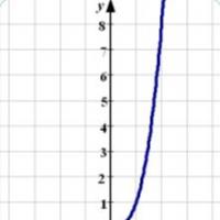 Quadratic and cubic functions
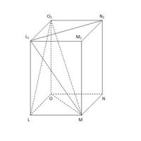 How to make a paper prism
 Everything you need to know about the prism for passing the exam in mathematics (2020)