Cable magazine GOST 21.408 93 download a sample. simplified way to execute automation schemes
INTERSTATE COUNCIL FOR STANDARDIZATION. METROLOGY AND CERTIFICATIONS
INTERSTATE COUNCIL FOR STANDARDIZATION. METROLOGY ANO CERTIFICATION
GOST 21.408 -
interstate standard
Official edition
Standardinform
Foreword
The goals, basic principles and basic procedure for work on interstate standardization are established by GOST 1.0-92 "Interstate system
standardization. Basic provisions ", and GOST 1.2-2009" System
interstate standardization. Interstate standards, rules and recommendations for interstate standardization. Rules for development, acceptance, application, updating and cancellation "
Information about the standard
1 DEVELOPED by the Open Joint Stock Company - Association "Montazhavto-Matika"
2 INTRODUCED by the Technical Committee for Standardization TC 465 "Construction"
3 ADOPTED by the Interstate Council for Standardization, Metrology and Certification (IGC) (Protocol No. 44-2013 dated November 14, 2013)
| Short name of the country according to MK (ISO 3166) 004-97 |
Country code according to MK (ISO 3166) 004-97 |
Abbreviated name of the state construction management body |
| Azerbaijan |
Aestandart |
|
| Ministry of Economy of the Republic of Armenia |
||
| Belarus |
State Standard of the Republic of Belarus |
|
| Kazakhstan |
Gosstandart of the Republic of Kazakhstan |
|
| Kyrgyzstan |
Kyrgyzstandard |
|
| Moldova-Standard |
||
| the Russian Federation |
Rosstandart |
|
| Tajikistan |
Taji "standard |
|
| Uzbekistan |
Uzstandart |
4 By order of the Federal Agency for Technical Regulation and Metrology of December 17, 2013 No. 2293-st, the interstate standard GOST 21.408-2013 was put into effect as a national standard of the Russian Federation from January 1, 2015.
4 REPLACE GOST 21.408-85
Information about changes to this standard is published in the annual information index "National Standards", and the text of changes and amendments is published in the monthly information index "National Standards". In case of revision (replacement) or cancellation of this standard, a corresponding notice will be published in the monthly information index "National Standards". Relevant information, notice and texts are also posted in the public information system - on the official website of the Federal Agency for Technical Regulation and Metrology on the Internet.
© Standartinform, 2014
In the Russian Federation, this standard cannot be fully or partially reproduced, replicated and distributed as an official publication without the permission of the Federal Agency for Technical Regulation and Metrology.
INTERSTATE STANDARD
System of design documents for construction
RULES FOR IMPLEMENTATION OF WORKING DOCUMENTATION OF AUTOMATION OF TECHNOLOGICAL PROCESSES
System of design documents for construction.
Rules of industrial process automation working documentation execution
Date of introduction - 2015-01-01
1 area of use
This standard establishes the composition and rules for drawing up working documentation for automation systems of technological processes and engineering systems, buildings and structures (hereinafter - automation systems) of projected construction objects for various purposes.
The requirements of this standard apply to the working documentation for the technical support of the automated process control system. developed in accordance with GOST 34.201.
graphic graphic. Feeding and dosing devices
GOST 2.795-80 Unified system for design documentation. Graphic designations. Centrifuges
GOST 8.417-2002 State system for ensuring the uniformity of measurements. Units of quantities
GOST 8.586.5-2005 Interstate standard State system for ensuring the uniformity of measurements Measurement of flow and quantity of liquids and gases using standard orifice devices Part 5 Measurement technique GOST 21.101-97 * System of design documentation for construction. Basic requirements for design and working documentation
GOST 21.110-2012 System of design documentation for construction. Specification of equipment, products and materials
Note - When using this standard, it is advisable to check the operation of the reference standards in the public information system - on the official website of the Federal Agency for Technical Regulation and Metrology on the Internet. or according to the annual information index "National Standards", which was published as of January 1 of the current year, and according to the issues of the monthly index "National Standards" for the current year.
If the reference standard is replaced (changed), then when using this standard, the replacing (modified) standard should be followed. If the reference standard is canceled without replacement, then the provision in which the reference to it is given applies to the extent not affecting this reference.
3 Terms, definitions and abbreviations
3.1 The following terms are used in this standard with the corresponding definitions and abbreviations:
3.1.1 automated process control system; APCS: A complex of software and hardware designed to automate the control of technological equipment at enterprises.
3.1.2 embedded structure: A part or assembly unit that is permanently embedded in building structures (channel, angle, sleeve, branch pipe, plate with sleeves, boxes with sand closure, suspended ceiling structures, etc.). into equipment or communications (lugs, sleeves, fittings, pockets, expanders, flange connections, counter flanges, transition pipes, etc.).
3.1.3 monitoring, regulation and control loop: A set of separate functionally related technical means of automation performing a specific task of monitoring, regulation, signaling, control, etc.
3.1.4 sampling device: A device (embedded structure) installed on process equipment or pipelines and designed to supply a controlled medium to instruments or measuring transducers or for installing instruments and transducers.
3.1.5 distributed control system: DCS: A technological process control system characterized by the construction of a distributed input / output system and decentralized data processing.
3.1.6 emergency automatic protection system; PAZ: A process control system that, in the event of a process going beyond a safe framework, performs a set of measures to protect equipment and personnel.
3.1.7 pipe wiring: A set of pipes (pipe cables), connections, connections, protective devices and fittings.
3.1.8 technical means of automation: The technical means of automation include devices, regulators, functional blocks, actuators, regulating bodies (hereinafter referred to as devices), as well as electrical devices, panels, consoles, complexes and other automation equipment.
4 General
4.1 Working documentation of automation systems is performed in accordance with the requirements of this standard. GOST 21.101 and other interrelated standards of the System of Design Documentation for Construction (SPDS) and the Unified System for Design Documentation (ESKD).
4.2 The composition of the working documentation for automation systems include:
Working drawings intended for the installation of automation equipment (the main set of working drawings for automation systems). The stamps of the main sets of working drawings are given in Appendix A;
Attached documents, including:
Questionnaires for devices and order cards for electrical devices, filled in according to the forms and instructions of manufacturers or suppliers. Questionnaires, order cards are handed over to the customer according to the statement separately from the rest of the working documentation of automation systems (CA);
Specification of equipment, products and materials:
Sketch drawings of general types of atypical automation equipment;
Local estimate.
4.3 In the drawings, the elements of automation systems are depicted in accordance with GOST 21.208, technological equipment, communications and building structures are depicted in a simplified way - with a solid thin line.
5 Basic set of working drawings for automation systems
5.1 Composition of the main set of working drawings for automation systems
5.1.1 8 the composition of the main set of working drawings for automation systems of grade A ... (hereinafter referred to as the main set) generally include:
General data on working drawings;
Automation schemes;
Principal (electrical, pneumatic) diagrams;
Diagrams (tables) of connections and external wiring connections;
Drawings of equipment location and external wiring;
Drawings of installations of automation equipment.
5.1.2 The composition of the documents being developed and their completeness for the APCS system and its parts should be determined in the terms of reference for the creation of an automated system (subsystem).
5.1.3 Control objects (departments, systems, installations, units, apparatuses) and related automation equipment that are not interconnected and have the same CA equipment. depict on the diagrams and location plans once, explaining with text instructions.
5.1.4 The main set is allowed to be drawn up as independent documents with the assignment of a basic designation, a mark of the main set and the addition (through a dot) of the serial number of the document (in Arabic numerals).
It is allowed to assign designations to the documents included in the set, in accordance with the coding system adopted by the organization.
Example - XXXX -XX - ATX1.1; XXXX -XX -ATX1.2 etc.
5.1.5 For objects with a small volume of installation work on automation, it is allowed to combine working drawings of automation of various technological processes and engineering systems into one main set. The combined master kit is designated AK.
5.1.6 In the case of using devices with radioisotope measurement methods, working drawings for their installation are separated into an independent main set.
5.1.7 Types, completeness and designation of documents when creating automated systems - in accordance with GOST 34.201.
5.2 General data on working drawings
5.2.2 In addition to the data specified in GOST 21.101, they include:
Table of initial data and calculation results of restricting devices (not supplied by the industry) in form 1 *;
Form 1 - Initial data and calculation results of orifice devices
End of Form 1
‘If the restriction devices are an integral part of the automation systems supplied complete with the equipment, the indicated table is not carried out.
Table of initial data and results of calculations of regulatory bodies in form 2 *;
Form 2-Initial data and results of calculations of regulatory bodies
The list of embedded structures, primary devices (placed on technological, sanitary and technical and other equipment and communications) according to Form 3. The list of embedded structures, primary devices and automation equipment includes:
Embedded structures intended for the installation of temperature measuring devices, selective pressure devices, level, composition and quality of a substance;
Primary devices (volumetric and high-speed meters, orifices, rotameters, flow meters and concentrators);
Float and displacer level transmitters and level switches;
Control valves.
* If the regulating bodies are an integral part of automation systems supplied complete with equipment, the indicated table is not followed.
Form 3 - List of embedded structures, primary devices
Notes (edit)
2 Drawings of embedded structures and drawings of the installation of devices are included in the attached documents of working drawings of the corresponding brand in accordance with GOST 21.101.
The list of embedded structures, devices and structures for laying pipe and electrical wiring and installing technical automation equipment according to Form 4. The list includes: embedded structures for installing cable structures and pipe and electrical wiring passages through walls and ceilings, structures for installing devices, actuators , switchboards, cable channels, racks for pipe and electrical wiring, rooms for placing switchboards and control points, analyzer and other rooms for placing automation equipment with an indication of the required climatic conditions.
5.2.3 When drawing up the main set of working drawings as separate documents, instead of working drawings of the main set, a list of documents in form 2 of GOST 21.101 is included in the general data. and in each of the subsequent documents of the main set, lists of working drawings of the document in form 1 of GOST 21.101 and a link to general data are given.
5.2.4 The general instructions give:
Information about the special characteristics of industrial safety of the designed facility;
Information about the classes and boundaries of explosive and fire hazardous zones in rooms and outdoor installations, about the categories and groups of explosive mixtures.
5.3 Automation schemes
5.3.1 Automation schemes are developed as a whole for a technological (engineering) system or part of it - a technological line, a block of equipment, an installation or a unit.
An automation scheme can be combined with a wiring diagram (wiring), performed as part of the main set of the TX brand in accordance with GOST 21.401, or with engineering systems diagrams - a basic technological automation diagram.
5.3.2 The automation diagram depicts:
Technological and engineering equipment and communications (pipelines, gas ducts, air ducts) of the automated facility (hereinafter referred to as the technological equipment);
Automation equipment or control, regulation and control loops;
Communication lines between individual automation equipment or circuits (if necessary). Communication lines between devices and control loops and
control, including wireless communication lines, are shown in the diagrams with conventional graphic symbols given in Table B.1 (Appendix B).
5.3.3 Process equipment on automation diagrams is recommended to be depicted in accordance with the connection diagram adopted in the main set of the TX brand or diagrams of engineering systems. At the same time, it is allowed to simplify images of technological equipment without showing equipment, communications and their elements on the diagram, which are not equipped with technical means of automation and do not affect the operation of automation systems.
5.3.4 Process equipment is depicted taking into account the requirements of the following standards:
Equipment - in accordance with GOST 2.780. GOST 2.782. GOST 2.788, GOST 2.789, GOST 2.790, GOST 2.791. GOST 2.792. GOST 2.793, GOST 2.794, GOST 2.795;
Shut-off valves used in automation systems (not control valves) - in accordance with GOST 2.785.
Conditional graphic and letter designations of instruments and control and management circuits are taken in accordance with GOST 21.208. The letter designations of the measured quantities and functional characteristics of the devices are indicated in the upper part of the conventional graphic designation.
5.3.5 Automation schemes are performed in two ways:
Expanded, in which the diagram shows the composition and location of the technical means of automation of each control and management loop;
Simplified, in which the diagram depicts the main functions of the monitoring and control loops (without highlighting the individual technical means of automation included in them and indicating the location).
5.3.6 Expanded way of executing automation schemes
5.3.6.1 Technological equipment is shown in the upper part of the diagram.
The conventional graphic designation of devices built into technological communications is shown in the break of the communication lines in accordance with Figure 1, and those installed on the technological equipment (using embedded devices) are shown side by side - in accordance with Figure 2. Conventional graphic designation of devices in accordance with GOST 21.208.
Picture 2
5.3.6.2 The rest of the technical means of automation are shown by conventional graphic symbols in the rectangles located at the bottom of the diagram. Each rectangle is assigned headings corresponding to the hardware shown in them.
The first is a rectangle, which shows off-board devices that are not structurally associated with technological equipment, with the heading "Local devices", below are rectangles in which boards and consoles are shown, as well as, if necessary, complexes of technical means, for example, a control panel, [ drawings V.Za, B.36 (Appendix B)], PAZ system shield.
The headers of the rectangles intended for the image of shields and consoles are taken in accordance with the names adopted in the outline drawings of general types, for complexes of technical means - in accordance with their entry in the specification of equipment, products and materials.
5.3.6.3 On the automation diagram, alphanumeric designations of devices are indicated in the lower part of a circle (square, rectangle) or on the right side of it, designations of electrical devices - to the right of their conventional graphic designation.
In this case, the designations of technical means are assigned according to the specification of equipment, products and materials and are composed of the digital designation of the corresponding contour and the letter designation (in capital letters) of each element included in the contour (depending on the sequence of signal transmission).
With a large number of devices, it is allowed to use designations in which the first character corresponds to the conventional designation of the measured quantity, the subsequent characters correspond to the ordinal number of the circuit within the measured quantity.
Electrical devices included in the automation system (bells, sirens, signal lamps, displays, electric motors, etc.) are shown on the diagram by graphical conventional
designations in accordance with GOST 2.722. GOST 2.732, GOST 2.741 and assign them alphanumeric designations in accordance with GOST 2.710.
5.3.6.4 Communication lines are allowed to be drawn with a break when they are long and / or when they are complexly located. Places of communication line breaks are numbered in Arabic numerals in the order of their location in a rectangle with the heading "Local devices".
Intersection of communication lines with images of technological equipment is allowed. Intersection of communication lines with device designations is not allowed.
5.3.6.5 The limiting (maximum or minimum) operating values of the measured (controlled) quantities in accordance with GOST 8.417 or in scale units of the selected device are indicated on the communication lines. To denote a rarefaction (vacuum), put a minus sign in front of the value of the measured (adjustable) values. For devices built directly into technological equipment and not having communication lines with other devices, the limit values of the quantities are indicated next to the designation of the devices.
5.3.6.6 Technological equipment is allowed not to be shown on the diagram in cases where the points of control and management in technological shops are few (for example, in the working documentation for dispatching). In this case, in the upper part of the diagram, instead of the image of the technological equipment, a table is given according to Figure 3, in the columns of which the name of the equipment and communications is indicated.
Entrance to the hydrogenation workshop_
Original product | Nitrogen
Figure 3
5.3.6.7 An example of the implementation of the automation scheme in a detailed way is shown in Figure B.1 (Appendix B).
5.3.7 Simplified way of executing automation schemes
5.3.7.1 An example of the execution of the automation scheme in a simplified way is shown in Figure B.2 (Appendix B).
5.3.7.2 With a simplified method of performing automation schemes, control and management loops, as well as single devices, are applied next to the image of technological equipment and communications (or in their break) according to Figures 1 and 2.
The contour table indicates the contour numbers and the sheet number of the main set. which shows the composition of each circuit.
5.3.7.3 The contour (regardless of the number of elements included in it) is depicted in the form of a circle (rectangle), separated by a horizontal line. In the upper part of the circle, write down the letter designation that determines the measured (adjustable) parameter, and the functions performed by this contour, in the lower part - the contour number. For the loops of automatic control systems, in addition, the diagram shows the actuators, regulating bodies and a communication line connecting the loops with the actuators.
The limiting operating values of the measured (controlled) quantities are indicated next to the graphic symbols of the contours or in the additional column of the contour table.
5.3.7.4 The composition of each circuit should be given on:
Principal (electrical, pneumatic) control, regulation and control scheme:
External wiring connection diagram.
5.3.7.5 When it is difficult to give the full composition of the contour elements on the automation diagrams, a block diagram of the contour is developed, an example of which is shown in Figure D.1 (Appendix D).
5.4 Schematic diagrams
5.4.1 Depending on the purpose and applied automation tools, the following are developed:
Basic electrical and pneumatic diagrams of control and control loops;
Schematic diagrams of electrical and pneumatic power supply ..
Basic electrical circuits for monitoring and control include
the main set when they are controlled from panels and consoles of automation systems.
It is allowed not to develop schematic diagrams of control and regulation loops if the interconnections of devices and devices included in them. are simple and unambiguous and can be shown in other drawings of the basic set. Allowed
combination of circuits for various functional purposes (for example, a power supply circuit with a control circuit) in compliance with the rules for performing these circuits, given below.
5.4.2 Basic electrical circuits are performed in accordance with GOST 2.701 and GOST 2.702. On electrical circuits, it is allowed:
Do not give the designations of the terminals of electrical devices, if they are given in the technical documentation for boards and consoles;
Do not include qualifying symbols in the designation of elements.
5.4.3 Schematic diagrams with the use of combined automation means (pneumatic and electrical) are performed in accordance with GOST 2.701.
5.4.4 On schematic diagrams, data on technical means are recorded in the list of elements in accordance with GOST 2.701.
It is allowed to write equipment into the list of elements in groups according to the places of their installation. These groups are assigned headings and indicated in the "Name" column, for example. "Apparatus in place", "Control panel", etc.
5.4.5 Pneumatic schematic diagrams.
5.4.5.1 The pneumatic diagrams of the monitoring and control circuits show:
Devices that make up the circuits:
Pneumatic command lines and pneumatic supply lines;
Power supply lines.
Pulse communication lines supplying the measured and controlled media to sensors, measuring instruments and regulators are not shown on pneumatic circuits.
5.4.5.2 Devices (with the exception of actuators and regulatory bodies depicted in accordance with GOST 21.208) are shown in the form of rectangles. At the same time, they show:
In circles located along the outline of the rectangle. - designations of input and output connections of devices (fittings) for connecting command communication and power lines, set in the technical documentation for the device, or on the corresponding diagram;
Inside the rectangle is the alphanumeric designation of the device.
5.4.5.3 Designations of the connecting nipples of the most common devices are given in Table 1.
Table 1
If the device has several connecting unions of the same purpose, then the serial number is included in their designation through a hyphen.
Example - 2-1, 2-2, 2-3.
5.4.5.4 The designation of the device consists of a letter designation corresponding to the functional purpose of the device and its serial number.
Example - RU1, RU2, F1, F2.
The letter designations of the most common devices and elements of pneumatic automation are taken in accordance with Appendix D.
5.4.5.5 Control stations and individual switching devices are performed in a simplified manner, in expanded form, in a selected operating position (manual, automatic, etc.) with an indication of the mode for which the switching device elements are given.
The regulating bodies are shown on the pneumatic circuit diagrams in cases where they are common with the actuators.
5.4.5.6 Communication lines are made with solid thin lines. Arrows indicate the direction of the pneumatic signal
5.4.5.7 The pneumatic power supply diagrams show:
Main and distribution manifolds;
Air duct networks from collectors to pneumatic receivers;
Air pressure stabilizers and filters:
Control pressure gauges;
Shut-off valves;
Back-up and purge valves;
Air collectors (if necessary).
On the principle pneumatic power supply diagrams, the air ducts are not numbered and the pneumatic receivers are not depicted. At the same time, in the lower part of the diagram, a table is given with the characteristics of pneumatic receivers (reference designations in accordance with the automation scheme, types, compressed air consumption, installation locations).
5.4.5.8 Graphical symbols used on power circuits, when
are taken according to the following standards:
Air filters ........................................... according to GOST 2.793;
Air pressure stabilizers ..................... in accordance with GOST 2.785;
Shut-off valves, three-way valves ............. in accordance with GOST 2.785;
Control pressure gauges ................................. in accordance with GOST 2.781;
Compressed air pipelines ........................ in accordance with GOST 2.784.
5.4.5.9 On the schematic diagrams of pneumatic supply, the nominal diameters of the pipes of the collectors and branches of the air lines to the pneumatic receivers are indicated. Above the line showing the manifold is the pressure, below the line is the compressed air consumption.
Examples of the execution of basic pneumatic diagrams are shown in Figures E.1, E.2 (Appendix E).
5.4.5.10 In the list of elements for pneumatic circuits, indicate:
In the column "Pos. designation "- device designation;
In the column "Name" - the name of the device and its type;
In the column "Note" - the designations of the devices indicated on the automation diagrams.
An example of the implementation of the list of elements is given in Table G.1 (Appendix G)
5.5 Functional diagrams of APCS, structural diagrams and others (in accordance with the terms of reference for the development of APCS)
This manual (RM) contains methodological recommendations for the design of automation schemes and structural diagrams of control and monitoring loops included in the working documentation of automation systems (SA) according to the recommendations of GOST 21.408 and RM 4-59. These recommendations are also applicable in the development of these schemes at the "project (working draft)" stage, as well as for automation schemes and block diagrams of control and control loops in the development of documentation for the technical support of automated process control systems (APCS) in accordance with GOST 34.201. When developing RM, the requirements and recommendations of the standards approved after the release of GOST 21.408 were also taken into account. Recommendations of the manual for the development of CA objects, which are subject to the requirements of SNiP 3.05.07 and GOST 21.408. (For an updated list of objects, see RM 4-59, Appendix 2). For the rest of the objects, this manual is applied to the extent that it does not contradict the special requirements of regulatory documents for the creation of the CA of these objects.
AUTOMATION SYSTEMS
AUTOMATION SCHEMES
IMPLEMENTATION INSTRUCTIONS
P special to GOST 21.408-93
PM4-2-96
GPKI "PROEKTMONTAZHAVTOMATIKA"
1996
Date of introduction 09/01/96
This manual (RM) contains guidelines for the design of automation schemes and structural diagrams of control and monitoring loops included in the working documentation of automation systems (SA) according to the recommendations of GOST 21.408 and RM4-59. These recommendations are also applicable in the development of these schemes at the "project (working project)" stage, as well as automation schemes and block diagrams of control and control loops in the development of documentation for the technical support of automated process control systems (APCS) in accordance with GOST 34.201. When developing RM, the requirements and recommendations of the standards approved after the release of GOST 21.408 were also taken into account.
The recommendations of the manual are used in the development of CA of objects that are subject to the requirements of SNiP 3.05.07 and GOST 21.408. (For an updated list of objects, see PM4-59, Appendix 2). For the rest of the objects, this manual is applied to the extent that it does not contradict the special requirements of regulatory documents for the creation of the CA of these objects.
one . BASIC PROVISIONS
1.1. The automation scheme is the main technical document that defines the structure (hierarchy) of control and management points, the functions of the control and management systems of the automated object, equipping the CA with technical means: automation devices and means, panels, consoles, computers, etc.
Automation schemes include in the main set of working documentation grade A ... in accordance with GOST 21.408, the stage "working documentation". On their basis, the development of the rest of the documentation for this stage is carried out.
When developing diagrams using CAD tools, the recommendations of clause 3.1.13 PM4-59 should be followed.
1.8. All the examples of automation schemes given in this RM cannot serve as examples for determining the scope of automation of technological processes and the composition of control and control loops. They are given only to illustrate the methods of designing schemes and cannot serve as reference data.
2. GENERAL RULES FOR IMPLEMENTATION OF AUTOMATION SCHEMES
In all cases of the development of a scheme for a part of the TOU, an assessment is made of the possibility of the subsequent application of these schemes in other sets of working documentation and (if necessary) they are released according to the recommendations of PM4-59, clause 2.12.
2.2. The automation diagram depicts:
1) a diagram of the technological process of the automation object - equipment and communications of the automated object (TOU);
2) automation systems - control loops, automatic regulation and control and the technical means included in them. In this case, a control, regulation and control loop is understood as a set of separate functionally related or independent devices and other technical means that perform a specific task of monitoring, regulation, signaling, control, etc .;
3) communication lines between individual technical means of automation in circuits or between circuits (if necessary);
4) the necessary explanations (tables of symbols, applicability; links to diagrams and drawings of adjacent taxiway sets, on the applicability of repeating elements of the circuit, etc.)
2.3. Control systems for equipment electric drives, which have no connection with the control and automatic control loops of the physical and chemical parameters of the TOU, are usually not shown on the automation schemes.
2.4. Automation schemes are performed in two ways:
1) expanded, in which the diagram shows the composition and location of the technical means of automation of each control and management loop;
2) simplified, in which the diagram depicts the main functions of the monitoring and control loops (without highlighting the individual technical means of automation included in them and indicating the location).
depict on the diagram the equipment and communications that are equipped with automation means for one circuit (or interconnected circuits), but the image of which in the technological (engineering) working documentation is given in different diagrams and drawings or in different basic sets.
Example: for the TOU of a boiler plant, it is recommended to provide a thermal diagram of the installation in accordance with GOST 21.606 and depict on it: air ducts and gas ducts based on the drawings for the arrangement of equipment, as well as gas pipelines according to the drawings of the main set of the GSV brand (according to GOST 21.609);
to simplify the image of the equipment without showing the equipment on the diagram (completely or its individual parts), communications and their elements, which are not equipped with technical means of automation and do not affect the operation of the CA.
Example: steam traps, silencers in plumbing systems, mud traps, safety devices.
Equipment - in accordance with GOST 2.790, GOST 2.791, GOST 2.792, GOST 2.793, GOST 2.794, GOST 2.795, GOST 21.205;
Communications depending on the transported media in accordance with Appendix 3 GOST 14202;
Crossings of pipeline communications - in accordance with GOST 21.206;
Pipeline valves used in automation systems (not control valves) - in accordance with GOST 21.205.
If necessary, images of views, sections and sections of equipment are performed in accordance with GOST 2.305, shading - in accordance with GOST 2.306.
2.5.3. Explanatory inscriptions (either the name of the equipment or their positions, if any on the technological scheme) should be given next to the image of the technological equipment.
Picture 1
2.8. Control objects of the same type (departments, systems, installations, units, apparatuses) that are not interconnected and have the same equipment with automation systems, the technical means of automation related to them are shown on the diagrams once.
The diagrams provide explanations.
Example. “The diagram is drawn up for unit 1; for units 2 - 5 the diagrams are similar. "
When executing an automation scheme on several sheets or when developing automation schemes for parts of technological systems, corresponding links are given on interconnected schemes (or its subsequent sheets).
Example. "Compressor automation scheme, see 16315-АХТ-015" or "Reactor automation scheme, see sheet 2".
2.9. On the automation diagram (on the first sheet, if the diagram is made on several sheets), explanations are given on the basis of which document it was developed.
Example. "The automation scheme was developed on the basis of the 34652-TX ... VNIIVProekt scheme."
symbols of technological communications;
Symbols of devices and automation equipment, which are not possible to depict according to the current standards;
alphanumeric abbreviations adopted for the symbols of individual units or devices (or the functions performed by them) of aggregated complexes, computers, sets (points) of telemechanics, etc.;
reserve letter designations used to designate controlled quantities or functional characteristics of devices that are absent in GOST 21.404.
Note. The use of the letter N to designate starting equipment in accordance with GOST 21.404 can be omitted.
Figure 3
3.1.4. The rest of the technical means of automation are shown with conventional graphic symbols in the rectangles located in the lower part of the diagram (below the image of the TOU). Each rectangle is assigned headings according to the guidelines below.
The first is a rectangle, which shows off-board devices that are not structurally related to technological equipment with the heading "Local devices", below are rectangles in which boards and consoles are shown, as well as complexes of technical means (if necessary).
The headings of the rectangles intended for the image of shields and consoles are indicated in accordance with the names adopted in the sketch drawings of general types, for complexes of technical means - in accordance with their entry in the specification of the equipment.
The devices used for control (regulation) are of the same type, the controlled parameters have different meanings; in this case, all devices should be shown on the board. Explanations are given about communication lines connecting devices and automation equipment with the controlled object (without the shown technological equipment). Example. "From reactors 2 - 3"(drawing ).
(monitored parameters have the same values)
Rice. 4
An example of the implementation of an automation scheme for the same type of technological objects with devices installed on a common panel (monitored parameters have different meanings)
Rice. 5
3.1.7. When using a multi-point device to control any parameter in several devices of the same type, only one technological device and one sensor are shown in the diagram, and communication lines from other sensors are shown near the device (figure).
An example of an image on the automation diagram of temperature measurement in several devices of the same type using a multi-point device
Rice. 6
An example of the implementation of the automation scheme using the pneumatic complex "Nominal"
Rice. 7
An example of the implementation of an automation scheme using an electronic computer (the technological part of the scheme is conventionally not shown)
Example. TI - telemetry, TS - telesignalization, TU - telecontrol, etc.
All accepted conventions must be deciphered on the diagram.
blocking with their small volume (no more than 3 - 4 x) show in the form of communication lines between contact devices of devices and equipment drives (or between interconnected drives) in case of their unambiguous effect;
for multi-mode control of electric drives with a large number of interdependencies - do not depict interlocks between different equipment, the switching on and off of which is carried out according to different interdependencies in the same mode or in different modes according to several (more than 3 - 4) parameters or with a complex combination of switching on and off interconnected equipment. In this case, instructions are given on the designations of circuit diagrams, in which they reflect all interlocks and modes;
to bring on the field of the automation scheme (or its subsequent sheets) schemes (tables) of locking dependencies;
depict control systems according to the rules for displaying aggregated complexes, computer facilities, telemechanics (see paragraphs;).
3.1.11. When the image of a shield or a complex of technical means is located on only one sheet, the rectangle of the shield on the right is closed with a line. If it is necessary to display them on subsequent sheets of one diagram or subsequent automation schemes, the image of these rectangles is not closed on the right side. The corresponding inscription is made in this place.
Example: When the image of the shield is located on three sheets, the inscription is made on the first sheet: "Sheet 2", on the second sheet - "Sheet 3", on the third sheet the rectangle of the shield is closed with a line.
Similar inscriptions are made on interconnected automation schemes that have common control points. In this case, instead of the sheet number, write the designation of the subsequent scheme. The name of the shield, located on the left on sheets 2 and 3 or subsequent diagrams, is performed in the same way as on sheet 1.
3.1.12. When developing complex multi-level automation systems in working documentation with the use of various equipment at each level (for example, design and company complexes for local information and control systems at the lower or middle level of control and personal computers - at the upper) it is recommended to additionally develop diagrams of structural complexes of technical means (CTS). The content of the diagram of the structural KTS is taken according to RD 50-34.698, an example of the implementation of the diagram is given in the appendix.
3.1.13. When developing design estimates for automation systems for objects designed using units or blocks of aggregated equipment, the following instructions must be additionally taken into account:
3.1.13.1. Automation devices and means located on the equipment block are shown on the block diagram (automation diagram, combined with the block equipment). Communication lines from devices on the block are displayed on the image of the contour (border) of the block.
Such schemes can be developed both in the design documentation of the block, and provided in the main sets of working drawings of the corresponding technical or engineering brands, and also developed as a task (part of a task) for the manufacture of a block.
3.1.13.2. The blocks on the TOU automation diagram are depicted in the form of a rectangle, to which the lines are drawn, indicating the technological communications connected to the block (figure). Inside the rectangle, there are inscriptions indicating the name and type of the block, as well as the designation of the automation scheme from the design documentation of the block or the block diagram according to the technological (engineering) documentation.
3.1.13.3. The outline of the rectangle shows the numbers (designations) of the communication lines from the devices installed on the block. The location of the communication line numbers in the rectangle should correspond to their location on the block diagrams. These lines connect to images of devices and automation equipment located in control centers.
3.1.13.4. The block automation scheme is executed in the form of a fragment of the technological scheme with the image of the devices and automation equipment installed on the block. The rules for the image of technological equipment and communications, as well as devices and automation equipment are adopted according to this RM. It is recommended to move the communication lines from the devices included in the blocks to the devices and automation equipment installed outside the block to one or two base lines located (if possible) below the technological equipment. The ends of the communication lines are marked with serial numbers from left to right, starting with the number 1.
An example of the implementation of an automation scheme using blocks of aggregated equipment
3.2.6. Communication lines should clearly display the functional connections of devices (elements) from the beginning of the signal (impact) to the end. If it is necessary to indicate the direction of signal transmission on communication lines, it is allowed to skew the arrows.
An example of implementation on the automation diagram of the intersection of communication lines with and without connection to each other
Rice. 10
3.2.7. For complex objects with a large number of used instruments and automation equipment, when the image of continuous communication lines makes it difficult to read the diagram, it is allowed to depict them with a break (address method of displaying communication lines). Places of communication line breaks are numbered in Arabic numerals in the order of their location in a rectangle with the heading "Local devices" or "Shield ..." (figure).
The combined execution of communication lines is allowed: by continuous lines and by the address method for those sections of the circuits where it is difficult to draw continuous lines.
3.2.10. Leader lines with shelves, used to record on them a brief explanation of the functions performed by the equipment, are depicted as shown in the diagram (see appendix).
An example of an image of communication line breaks
Rice. eleven
3.2.11. At the ends of communication lines passing from one sheet of the diagram to another sheet or diagram, indicate the sheet number or designation of the diagram, where the continuation of these lines is shown. Such explanations are given on each of the interconnected sheets or diagrams (see figure) .
3.3. Positional designations of devices, automation and electrical devices.
3.3.1. Positional designations of devices and automation equipment should consist, as a rule, of two parts: a digital designation assigned to the monitoring and control circuit, and a letter designation (in capital letters of the Russian alphabet) assigned to each individual element included in the circuit in alphabetical order, depending on the sequence signal passage (from the device for receiving information to devices for influencing the controlled process).
1) devices for control and regulation (temperature, pressure and vacuum, flow rate, quantity, level, composition and quality of the substance);
2) other devices, regulators, complete devices.
3.3.6. Contours consisting of several sensors and one secondary device are assigned a reference designation containing a common numeric designation and several letter designations. At the same time, the same letter designations should be assigned to the same sensors, and different letters to different ones. The secondary device is assigned a subsequent letter designation.
3.3.7. The procedure for assigning reference designations to devices and automation equipment in the control and management circuits operating in conjunction with the technical means of the control computer complex (UVK) is taken in accordance with the above paragraphs.
3.3.8. It is recommended that local devices of the same type and characteristics be assigned the same reference designations, regardless of their installation location.
3.3.9. Identical contours and their elements installed on the same type of equipment are assigned the same reference designations. Identical contours and their elements installed on different types of equipment are assigned different reference designations.
For joining automation circuits with circuit diagrams, on which the output device of instruments and automation equipment is assigned reference designations in accordance with GOST 2.710 and RM4-105, the reference designations of devices according to the specification of equipment, products and materials are indicated in the "Note" column of the list of elements of the corresponding circuit diagram ...
4 . SIMPLIFIED METHOD FOR PERFORMANCE OF AUTOMATION SCHEMES
4.1. With a simplified method of performing automation schemes, control and management contours are applied to them, as well as single devices, they are applied next to the image of technological equipment and communications (or in their break) according to drawings and. The composition of the technical means of the contour is given in other sheets (documents) of the main set.
At the bottom of the diagram, it is recommended to give a table of contours in accordance with the application. The contour table indicates the contour numbers and the sheet number (document designation) of the main set, which shows the composition of each contour.
4.2. The contour (regardless of the number of elements included in it) is depicted in the form of a circle (oval), separated by a horizontal line. The letter designation is written in the upper part of the circle, which determines the measured (adjustable) parameter and the functions performed by this contour, in the lower part - the contour number. For the circuits of automatic control systems, in addition, the diagram shows the actuators, regulating bodies and a communication line connecting the circuit with the actuators.
The limiting operating values of the measured (controlled) quantities are indicated next to the graphic symbols of the contours or in the additional column of the contour table.
4.3. The composition of each circuit should be shown on:
Principal (electrical, pneumatic) control, regulation and control scheme;
External wiring connection diagram.
4.4. When it is difficult to give the full composition of the contour elements on the indicated diagrams, a structural circuit diagram of the contour is developed, an example of which is shown in the figure.
4.5. An example of the execution of the automation scheme in a simplified way is given in the appendix.
An example of an image of the composition of the circuit for measuring, regulating and signaling the level on the structural diagram of the KTS
Rice. 12
4.6. The table of contours, depending on the volume of automation, can be located either on a free field of the automation scheme (application), or on subsequent sheets of the A4 format scheme (figure).
Single devices are not included in the table. Contours having the same composition, which can be depicted on one document, are entered into the table once. In this case, in the column "Number of the contour" enumerate the designations of these contours.
In doing so, the following rules should be observed:
1) the circuit is performed in compliance with the general rules for the image of devices, wiring, etc. according to PM4 - 6 h. III;
2) devices installed on boards, consoles, complexes are depicted using mounting symbols by analogy with the image of local devices;
3) for wiring combined into trunk streams, connection to junction boxes, panels, etc. Shown conditionally (without terminal clamps). Their actual connection is displayed on the general diagram of connections of external wiring, which shows the structure of combining wiring from individual circuits into streams. An example of an image of the composition of the flow measurement circuit on the external wiring connection diagram is shown in the figure (the type of the junction box, pos. 4 and the cable, pos. 5, is not indicated, since these data are shown in the general diagram of the external wiring connections).
An example of the execution of the table of contours, located on the subsequent sheets of the automation scheme
|
Circuit no. |
|
|
Circuit no. |
Designation of the project document |
Limit value of the measured (controlled) value |
|
1 |
XXX-AHT-XX |
... ° C |
13 |
XXX-AHT-XX |
... m 3 / h |
|
2 |
XXX-ATX-XX |
... ° C |
14 |
UO4.XXX.XX |
... m 3 / h |
|
3 |
XXX-AHT-XX |
... ° C |
15 |
XXX-AHT-XX |
... m |
|
4 |
XXX-AHT-XX |
... ° C |
16 |
XXX-AHT-XX |
... m |
|
5 |
XXX-AOB-XX |
... ° C |
17 |
XXX-AHT-XX |
... m |
|
6 |
XXX-AHT-XX |
... MPa |
18 |
XXX-AHT-XX |
mg / l |
|
7 |
XXX-AHT-XX |
... MPa |
|||
|
8 |
XXX-AOB-XX |
... MPa |
|||
|
9 |
UO4.XXX.XX |
... MPa |
|||
|
10 |
UO4.XXX.XX |
... MPa |
|||
|
11 |
XXX-AHT-XX |
... m 3 / h |
|||
|
12 |
XXX-AHT-XX |
... m 3 / h |
Rice. thirteen
An example of an image of the composition of the flow measurement circuit on the external wiring connection diagram
|
Pos. designation. |
Name |
Qty. |
Note. |
|
1 |
Seamless steel pipe |
||
|
2 |
Shut-off valve V-501 d y = 10 mm |
4 |
|
|
3 |
Control cable KVVG 5 ´ 1,0 |
||
|
4 |
Junction box |
||
|
5 |
Control cable |
1) the main inscription on the documents is performed in accordance with Form 3 of GOST 21.101;
2) re-use documents are named by type:
ATS circuit of temperature.
Electrical schematic diagram;
Flow measurement circuit.
External wiring connection diagram;
Level measurement and signaling circuit.
Structural diagram of the CTS;
3) documents of reuse are recorded in the list of reference and attached documents in accordance with GOST 21.101 (in the section "Attached documents");
4) if there are variable data in the documents, (positions and types of devices, designations of elements and circuits, markings, types and lengths of wiring, etc.), they are presented in the contour applicability table (figure).
4.14. The contour applicability tables are developed by independent text documents in compliance with the following rules:
1) the name of the tables should consist of the name of the circuit of the corresponding circuit (p.) And the words: "Table of applicability";
1) a graphic representation of the composition of the contour and its connections;
2) the form of the applicability table;
3) the main inscription in accordance with GOST 21.101 (form 1), on which it is recommended to fill in columns 4, 7, 8.
The form should be made on tracing paper using an electrographic method to ensure good, clear copies.
The development of contour diagrams in this case is reduced to filling the applicability table with the necessary variable data and the remaining unfilled column of the title block.
An example of the implementation of the applicability table of the flow measurement circuit diagram
|
Pos. diaphragm |
Pos. differential pressure gauge |
Valve type |
Pipe |
Cable |
||||||||||||||||||||||||||||||||||||||||||||||||||||||||||||||||||||||||||||||||||||||||||||||||||||||||||||||||||||||||||||||||||||||||||||||||||||||||||||||||||
|
Brand |
Length |
Brand |
Length |
|||||||||||||||||||||||||||||||||||||||||||||||||||||||||||||||||||||||||||||||||||||||||||||||||||||||||||||||||||||||||||||||||||||||||||||||||||||||||||||||||||
|
34a |
34b |
B-501; d y = 10 |
Pipe 14 ´ 2 GOST 8734-75 |
KRVG 5 ´ 1 GOST 1508-78 |
||||||||||||||||||||||||||||||||||||||||||||||||||||||||||||||||||||||||||||||||||||||||||||||||||||||||||||||||||||||||||||||||||||||||||||||||||||||||||||||||||
|
35a |
35b |
Also |
Too |
Too |
||||||||||||||||||||||||||||||||||||||||||||||||||||||||||||||||||||||||||||||||||||||||||||||||||||||||||||||||||||||||||||||||||||||||||||||||||||||||||||||||||
|
36a |
36b |
|||||||||||||||||||||||||||||||||||||||||||||||||||||||||||||||||||||||||||||||||||||||||||||||||||||||||||||||||||||||||||||||||||||||||||||||||||||||||||||||||||||
|
37a |
37b |
|||||||||||||||||||||||||||||||||||||||||||||||||||||||||||||||||||||||||||||||||||||||||||||||||||||||||||||||||||||||||||||||||||||||||||||||||||||||||||||||||||||
|
38a |
38b |
|||||||||||||||||||||||||||||||||||||||||||||||||||||||||||||||||||||||||||||||||||||||||||||||||||||||||||||||||||||||||||||||||||||||||||||||||||||||||||||||||||||
|
39a |
39b |
|||||||||||||||||||||||||||||||||||||||||||||||||||||||||||||||||||||||||||||||||||||||||||||||||||||||||||||||||||||||||||||||||||||||||||||||||||||||||||||||||||||
|
134a |
134b |
14nzh 19p d y = 10 |
Pipe 14 ´ 2 17Х18Н9 GOST 9941-81 |
KRVG 5 ´ 1 GOST 1508-781 |
GOST 21.408-93 UDC 691: 002: 006: 354 Ж01 INTERSTATE STANDARD System of design documents for construction RULES FOR IMPLEMENTATION OF WORKING DOCUMENTATION AUTOMATION OF TECHNOLOGICAL PROCESSES System of design documents for construction. Roles of industrial process automation working documentation execution OKSTU 0021 Date of introduction 1994-12-01 Foreword 1 DEVELOPED by the State Design and Design Institute "Proektmontazhavtomatika" and the Central Research and Design and Experimental Institute on Methodology, Organization, Economics and Design Automation (TsNIIproekt) INTRODUCED by Gosstroy of Russia 2 ADOPTED by the Interstate Scientific and Technical Commission for Standardization and Technical Regulation in Construction on November 10, 1993
3 INTRODUCED IN THE FIRST 4 PUT INTO EFFECT from December 1, 1994 as a state standard of the Russian Federation by the decree of the Gosstroy of Russia dated April 5, 1994 No. 18-26 1 AREA OF USE This standard establishes the composition and rules for the design of working documentation for automation systems of technological processes and engineering systems (hereinafter - automation systems) of projected construction objects for various purposes. The requirements of this standard apply to the working documentation for the technical support of the automated process control system, developed in accordance with GOST 34.201. The standard does not apply to working documents for automation systems for centralized power supply management. Throughout this standard, references are made to the following standards: GOST 2.701-84 ESKD. Scheme. Types and types. General requirements for implementation GOST 2.702-75 ESKD. Rules for the implementation of electrical circuits GOST 2.710-81 ESKD. Alphanumeric designations in electrical circuits GOST 2.722-69 ESKD. Conditional graphic designations in schemes. Electrical machines GOST 2.732-68 ESKD. Conditional graphic designations in schemes. Sources of light GOST 2.741-68 ESKD. Conditional graphic designations in schemes. Acoustic devices GOST 2.780-68 ESKD. Conditional graphic designations in schemes. Elements of hydraulic and pneumatic networks GOST 2.781-68 ESKD. Conditional graphic designations in schemes. Hydraulic and pneumatic guiding and regulating devices, instrumentation and control devices GOST 2.782-68 ESKD. Graphic designations. Pumps and motors, hydraulic and pneumatic GOST 2.784-70 ESKD. Graphic designations. Elements of pipelines GOST 2.785-70 ESKD. Graphic designations. Pipe fittings GOST 2.788-74 ESKD. Graphic designations. Evaporators GOST 2.789-74 ESKD. Graphic designations. Heat exchangers GOST 2.790-74 ESKD. Graphic designations. Column apparatuses GOST 2.791-74 ESKD. Graphic designations. Sediments and filters GOST 2.792-74 ESKD. Graphic designations. Dryers GOST 2.793-79 ESKD. Graphic designations. Elements and devices of machines and apparatus of chemical production. General notation GOST 2.794-79 ESKD. Graphic designations. Feeding and dosing devices GOST 2.795-80 ESKD. Graphic designations. Centrifuges GOST 8.417-81 GSI. Physical units GOST 21.101-93 SPDS. Basic requirements for working documentation GOST 21.110-95 SPDS. Rules for the implementation of the specification of equipment, products and materials GOST 21.401-88 SPDS. Production technology. Basic requirements for working drawings GOST 21.404-85 SPDS. Automation of technological processes. Symbols of conventional devices and automation equipment in diagrams GOST 21.614-88 SPDS. Conditional graphic images of electrical equipment and wiring on plans GOST 34.201-89 Information technology. Set of standards for automated systems. Types, completeness and designation of documents when creating automated systems GOST 14202-69 Industrial pipelines. Identification colors, warning signs and marking plates 3 GENERAL PROVISIONS 3.1 Working documentation of automation systems is carried out in accordance with the requirements of this standard, GOST 21.101 and other interrelated standards of the System of design documentation for construction (SPDS) and the Unified system of design documentation (ESKD). 3.2 The working documentation for automation systems includes: Working drawings intended for the installation of automation equipment * (basic sets of working drawings for automation systems of grades A ..., given in Appendix A); Sketch drawings of general types of atypical automation equipment; Specification of equipment, products and materials (hereinafter - equipment specification). __________________ * The technical means of automation include devices, regulators, functional blocks, actuators, regulating bodies (hereinafter referred to as devices), as well as electrical devices, panels, consoles, complexes and other automation equipment 3.3 Simultaneously with the working documentation of automation systems, they develop technical documentation for the manufacture and delivery of technical automation equipment to the construction site, including: Questionnaires for devices; Order cards for electrical devices; Tables of connections and wiring connections in boards and consoles *; Documentation for ordering complexes of means of centralized control and regulation, telemechanics, computers, software and hardware complexes, microprocessor tools and controllers, systems and installations of pneumatic automation, etc. (hereinafter - complexes of technical means **). ________________ * Perform if necessary ** Executed at the request of the customer 3.4 In the drawings and diagrams, the elements of automation systems are depicted with a solid thick main line, technological equipment, communications and building structures are depicted in a simplified way - with a solid thin line. 4 BASIC DRAWING SET OF AUTOMATION SYSTEMS 4.1 Composition of the main set of working drawings for automation systems 4.1.1 The main set of working drawings for automation systems of grade A ... (hereinafter the main set) generally includes: General data on working drawings; Automation schemes; Schematic diagrams (electrical, pneumatic); Diagrams (tables) of connections and external wiring connections; Drawings of equipment location and external wiring; Drawings of installations of automation equipment. 4.1.2 Control objects (departments, systems, installations, units, apparatuses) and related automation tools, not interconnected and having the same equipment with automation systems, are depicted on the diagrams and layout plans once, explaining with text instructions. 4.1.3 The main set is allowed to be drawn up as independent documents with the assignment of a basic designation, a mark of the main set and the addition (through a dot) of the serial number of the document (in Arabic numerals). Example - XXXX - XX - ATX1.1; XXXX - XX - ATX1.2 etc. 4.1.4 For objects with a small volume of installation work on automation, it is allowed to combine working drawings of automation of various technological processes and engineering systems into one main set, if their installation is carried out by one installation organization. The combined master kit is designated AK. 4.1.5 In the case of using devices with radioisotope measurement methods, working drawings for their installation are separated into an independent main set. 4.2 General data on working drawings 4.2.1 General data on working drawings (hereinafter referred to as general data) are performed in accordance with GOST 21.101. In this case, the specification sheet is not drawn up. 4.2.2 In addition to the data specified in GOST 21.101, they include: Table of initial data and calculation results of restricting devices (not supplied by the industry) in form 1 *; Table of initial data and results of calculations of regulatory bodies in form 2 *; The list of embedded structures, primary devices (placed on technological, sanitary-technical and other equipment and communications) in form 3. __________________________ * If the restriction devices and regulating bodies are part of the automation systems supplied complete with the equipment, the indicated tables are not met. The list of embedded structures, primary devices and automation equipment includes: Embedded structures intended for the installation of temperature measuring devices, selective pressure devices, level, composition and quality of a substance; Primary devices (volumetric and high-speed meters, orifices, rotameters, flow meters and concentrators); Float and displacer level transmitters and level switches; Control valves. 4.2.3 When the main set is drawn up with separate documents, the general data include a list of documents in form 2 of GOST 21.101, and in each of the subsequent documents - a list of working drawings of the document in form 1 of GOST 21.101 and a link to general data. Form 1 Initial data and calculation results of orifice devices Form 2 Initial data and results of calculations of regulatory bodies
Form 3 List of embedded structures, primary devices
4.3 Automation schemes 4.3.1 Automation schemes are developed as a whole for a technological (engineering) system or part of it - a technological line, a block of equipment, an installation or a unit. The automation scheme can be combined with the wiring diagram (wiring), performed as part of the main set of the TX brand in accordance with GOST 21.401, or with engineering systems diagrams. 4.3.2 The automation diagram depicts: 1) technological and engineering equipment and communications (pipelines, gas ducts, air ducts) of the automated facility (hereinafter referred to as technological equipment); 2) technical means of automation or control, regulation and control loops *; 3) communication lines between individual technical automation equipment or circuits (if necessary). ___________________________ * A control, regulation and control loop is a collection of separate functionally related devices performing a specific task for monitoring, regulation, signaling, control, etc. 4.3.3 Process equipment on automation diagrams is recommended to be depicted in accordance with the connection diagram adopted in the main set of the TX brand or diagrams of engineering systems. At the same time, it is allowed to simplify images of technological equipment without showing equipment, communications and their elements on the diagram, which are not equipped with technical means of automation and do not affect the operation of automation systems. 4.3.4 In the absence of the TX brand in the main set of the connection diagrams, the technological equipment is depicted taking into account the requirements of the following standards: Equipment - in accordance with GOST 2.780, GOST 2.782, GOST 2.788, GOST 2.789, GOST 2.790, GOST 2.791, GOST 2.792, GOST 2.793, GOST 2.794, GOST 2.795; Communications depending on the transported media in accordance with Appendix 3 GOST 14202; Shut-off valves used in automation systems (not control valves) - in accordance with GOST 2.785. Conditional graphic and letter designations of instruments and control and management circuits are taken in accordance with GOST 21.404. The letter designations of the measured values and the functional characteristics of the devices are indicated in the upper part of the circle (oval). The communication lines between the devices and the monitoring and control circuits are shown in the diagrams with a solid thin line, regardless of the type of signals and the number of wires and pipes. 4.3.5 Automation schemes are performed in two ways: 1) expanded, in which the diagram shows the composition and location of the technical means of automation of each control and management loop. 2) simplified, in which the diagram depicts the main functions of the monitoring and control loops (without highlighting the individual technical means of automation included in them and indicating the location). 4.3.6 Expanded method of execution of automation schemes 4.3.6.1 Technological equipment is shown in the upper part of the diagram. Devices built into technological communications are shown in a break in the lines of communication images in accordance with Figure 1, installed on technological equipment (using embedded devices) are shown next to them - in accordance with Figure 2.
Picture 1
Picture 2 4.3.6.2 The rest of the technical means of automation are shown with conventional graphic symbols in the rectangles located at the bottom of the diagram. Each rectangle is assigned headings corresponding to the hardware shown in them. The first is a rectangle, which shows off-board devices that are not structurally connected with technological equipment, with the heading "Local devices", below - rectangles in which boards and consoles are shown, as well as complexes of technical means (if necessary). The headers of the rectangles intended for the image of boards and consoles are taken in accordance with the names adopted in the outline drawings of general types, for complexes of technical means - in accordance with their entry in the equipment specification. 4.3.6.3 On the automation diagram, alphanumeric designations of devices are indicated in the lower part of a circle (oval) or on the right side of it, designations of electrical devices - to the right of their conventional graphic designation. In this case, the designations of technical means are assigned according to the equipment specification and are composed of the digital designation of the corresponding contour and the letter designation (in capital letters of the Russian alphabet) of each element included in the contour (depending on the sequence of signal transmission). With a large number of devices, it is allowed to use designations in which the first character corresponds to the conventional designation of the measured quantity, the subsequent characters correspond to the ordinal number of the circuit within the measured quantity. Electrical devices included in the automation system (bells, sirens, signal lamps, panels, electric motors, etc.) are shown on the diagram with graphical symbols in accordance with GOST 2.722, GOST 2.732, GOST 2.741 and assign them alphanumeric designations in accordance with GOST 2.710. 4.3.6.4 Communication lines are allowed to be drawn with a break when they are long and / or when they are complexly located. Places of communication line breaks are numbered in Arabic numerals in the order of their location in a rectangle with the heading "Local devices". Intersection of communication lines with images of technological equipment is allowed. Intersection of communication lines with device designations is not allowed. 4.3.6.5 The limiting (maximum or minimum) operating values of the measured (controlled) quantities in accordance with GOST 8.417 or in scale units of the selected device are indicated on the communication lines. To denote rarefaction (vacuum), put a "minus". For devices built directly into technological equipment and not having communication lines with other devices, the limit values of the quantities are indicated next to the designation of the devices. 4.3.6.6 Technological equipment is allowed not to be shown on the diagram in cases where the points of control and management in technological shops are few (for example, in the working documentation for dispatching). In this case, in the upper part of the diagram, instead of the image of the technological equipment, a table is given according to Figure 3, in the columns of which the name of the equipment and communications is indicated.
Figure 3 6.7 An example of executing an automation scheme in a detailed way is given in Appendix B. 4.3.7 Simplified way to execute automation schemes 4.3.7.1 With a simplified method of performing automation schemes, control and management loops, as well as single devices, are applied next to the image of technological equipment and communications (or in their break) according to Figures 1 and 2. At the bottom of the diagram, it is recommended to provide a table of contours in accordance with Appendix B. The contour numbers and the number of the sheet of the main set, which shows the composition of each contour, are indicated in the table of contours. 4.3.7.2 The contour (regardless of the number of elements included in it) is depicted in the form of a circle (oval), separated by a horizontal line. The letter designation is written in the upper part of the circle, which determines the measured (adjustable) parameter and the functions performed by this contour, in the lower part - the contour number. For the loops of automatic control systems, in addition, the diagram shows the actuators, regulating bodies and a communication line connecting the loops with the actuators. The limiting operating values of the measured (controlled) quantities are indicated next to the graphic symbols of the contours or in the additional column of the contour table. 4.3.7.3 The composition of each circuit should be given on: Principal (electrical, pneumatic) control, regulation and control scheme; External wiring connection diagram. An example of a structural diagram
Figure 4 4.3.7.4 When it is difficult to give the full composition of the contour elements on automation diagrams, a structural circuit diagram of the contour is developed, an example of which is shown in Figure 4. 4.3.7.5 An example of the execution of the automation scheme in a simplified way is given in Appendix B. 4.4 Schematic diagrams 4.4.1 Depending on the purpose and applied automation tools, the following are developed: Basic electrical and pneumatic diagrams of control and control loops; Schematic diagrams of power supply. Basic electrical circuits for controlling electric drives of equipment and pipeline fittings are included in the main set when they are controlled from panels and consoles of automation systems. It is allowed not to develop schematic diagrams of control and regulation loops if the interconnections of the devices and devices included in them are simple and unambiguous and can be shown in other drawings of the main set. It is allowed to combine circuits of various functional purposes (for example, a power supply circuit with a control circuit) in compliance with the rules for the implementation of these circuits, given below. 4.4.2 Electrical circuits are performed in accordance with GOST 2.701 and GOST 2.702. On electrical circuits, it is allowed: Do not give the designations of the terminals of electrical devices, if they are given in the technical documentation for boards and consoles; Do not include qualifying symbols in the designation of elements. 4.4.3 Circuits using combined automation (pneumatic and electrical) are performed in accordance with GOST 2.701. 4.4.4 On schematic diagrams, data on technical means are recorded in the list of elements in accordance with GOST 2.701. It is allowed to write equipment into the list of elements in groups according to the places of their installation. These groups are assigned headings and indicated in the "Name" column. Example - "Apparatus in place", "Control panel", etc. 4.4.5 The pneumatic diagrams of the monitoring and control circuits show: Devices that are part of the circuits; Pneumatic command lines and pneumatic supply lines; Power supply lines. Pulse communication lines supplying the measured and controlled media to sensors, measuring instruments and regulators are not shown on pneumatic circuits. 4.4.6 Devices (with the exception of actuators and regulatory bodies depicted in accordance with GOST 21.404) are shown in a simplified manner in the form of rectangles. At the same time, they show: In the circles located along the contour of the rectangle - designations of the input and output connections of devices (fittings) for connecting command communication and power lines, installed in the technical documentation for the device, or on the corresponding diagram; Inside the rectangle is the alphanumeric designation of the device. 4.4.7 Designations of the connecting nipples of the most common devices are given in Table 1. Table 1
If the device has several connecting unions of the same purpose, then the serial number is included in their designation through a hyphen. Example - 2-1, 2-2, 2-3; 4.4.8 The designation of the device consists of a letter designation corresponding to the functional purpose of the device and its serial number. Example - RU1, RU2, F1, F2. The letter designations of the most common devices and elements of pneumatic automation are taken according to table 2. table 2
4.4.9 Control stations and individual switching devices are performed in a simplified manner, in expanded form, in a selected operating position (manual, automatic, etc.) with an indication of the mode for which the switching device elements are given. Regulatory bodies are shown on diagrams in cases where they are common with actuators. 4.4.10 Communication lines on pneumatic circuits are performed with solid thin lines, power supply lines - with dash-dotted thin lines. The arrows indicate the direction of the pneumatic signal. Compressed air supply lines, power supply lines and air discharge into the atmosphere are allowed to be applied according to Figure 5.
Figure 5 4.4.11 Pneumatic power supply circuits show: Main and distribution manifolds; Air duct networks from collectors to pneumatic receivers; Air pressure stabilizers and filters; Control pressure gauges; Shut-off valves; Back-up and purge valves; Air collectors (if necessary). On the power supply diagrams, the air ducts are not numbered and the pneumatic receivers are not shown. At the same time, in the lower part of the diagram, a table is given with the characteristics of pneumatic receivers (reference designations in accordance with the automation scheme, types, compressed air consumption, installation locations). 4.4.12 Graphic symbols used on power circuits are adopted according to the following standards: 4.4.13 On the pneumatic supply diagrams, the nominal diameters of the pipes of the collectors and branches of the air lines to the pneumatic receivers are indicated. Above the line showing the manifold is the pressure, below the line is the compressed air consumption. 4.4.14 In the list of elements for pneumatic circuits, indicate: In the column "Pos. Designation" - the designation of the device according to 4.4.8; In the column "Name" - the name of the device and its type; In the "Note" column - the designations of the devices indicated on the automation diagrams. An example of the implementation of the list of elements is shown in Figure 6.
Figure 6 4.4.15 Examples of the execution of basic pneumatic diagrams are given in Appendices D and D. 4.5 Diagrams (tables) of connections and external wiring connections 4.5.1 General requirements 4.5.1.1 Connections and connections of external wiring are shown in the form of diagrams or tables. 4.5.1.2 Connection diagrams and connections are performed, as a rule, separately for each automated unit, the installation of which is carried out independently of the others. In this case, the name of the block is additionally indicated in the name of the circuit. EXAMPLE Pump block. External wiring connection diagram. 4.5.1.3 It is recommended on the external wiring connection diagrams to bring electrical wiring connections to devices installed directly on technological equipment and communications, as well as to single off-panel (local) devices. With an insignificant amount of electrical wiring connected to the technical means of automation, these connections can be shown in the connection diagram without performing the connection diagrams. 4.5.1.4 Connections of electrical wiring to group installations of devices, boards and consoles, complexes of technical means are recommended to be provided on independent connection diagrams. 4.5.1.5 Technical means, for which the wiring connections are shown on the diagrams, are depicted in a simplified way by external outlines or in the form of rectangles, in which: Introductory elements (for example, sealed glands, glands) - along the contour of the rectangle are shown with conventional graphic symbols in accordance with GOST 2.702; Input and output elements are shown in the form of circles (for round plug connectors) or rectangles (for example, for assemblies and terminal blocks and other elements of the corresponding shape). 4.5.1.6. The designations (of off-panel devices), the serial number and type (of junction boxes) are indicated above the shelf of the leader line, under the shelf - the designation and / or number of the installation sheet (Figure 7)
Figure 7 For the rest of the technical means, inside the rectangle indicate their name, as well as: Sheet number (document designation) of the installation drawing (for group installation); Designation of a sketch drawing of a general view (for panels and consoles). 4.5.1.7 The designation of the conductors of cables and wires on the diagrams and tables of connections and connections is taken in accordance with the schematic electrical diagrams. 4.5.2 Rules for the implementation of connection diagrams of external wiring 4.5.2.1 In the connection diagram, in the general case, give: Primary devices and actuators installed directly on technological equipment and communications; Off-panel devices and group installations of devices; Boards, consoles, complexes of technical means; External electrical and pipe wiring between all technical automation equipment; GOST 21.408-93 UDC 691: 002: 006: 354 Ж01 INTERSTATE STANDARD System of design documents for construction RULES FOR IMPLEMENTATION OF WORKING DOCUMENTATION AUTOMATION OF TECHNOLOGICAL PROCESSES System of design documents for construction. Roles of industrial process automation working documentation execution Date of introduction 1994-12-01 Foreword 1 DEVELOPED by the State Design and Design Institute "Proektmontazhavtomatika" and the Central Research and Design and Experimental Institute on Methodology, Organization, Economics and Design Automation (TsNIIproekt) INTRODUCED by Gosstroy of Russia 2 ADOPTED by the Interstate Scientific and Technical Commission for Standardization and Technical Regulation in Construction on November 10, 1993
3 INTRODUCED IN THE FIRST 4 PUT INTO EFFECT from December 1, 1994 as a state standard of the Russian Federation by the decree of the Gosstroy of Russia dated April 5, 1994 No. 18-26 1 AREA OF USE This standard establishes the composition and rules for the design of working documentation for automation systems of technological processes and engineering systems (hereinafter - automation systems) of projected construction objects for various purposes. The requirements of this standard apply to the working documentation for the technical support of the automated process control system, developed in accordance with GOST 34.201. The standard does not apply to working documents for automation systems for centralized power supply management. GOST 2.701-84 ESKD. Scheme. Types and types. General requirements for implementation GOST 2.702-75 ESKD. Rules for the implementation of electrical circuits GOST 2.710-81 ESKD. Alphanumeric designations in electrical circuits GOST 2.722-69 ESKD. Conditional graphic designations in schemes. Electrical machines GOST 2.732-68 ESKD. Conditional graphic designations in schemes. Sources of light GOST 2.741-68 ESKD. Conditional graphic designations in schemes. Acoustic devices GOST 2.780-68 ESKD. Conditional graphic designations in schemes. Elements of hydraulic and pneumatic networks GOST 2.781-68 ESKD. Conditional graphic designations in schemes. Hydraulic and pneumatic guiding and regulating devices, instrumentation and control devices GOST 2.782-68 ESKD. Graphic designations. Pumps and motors, hydraulic and pneumatic GOST 2.784-70 ESKD. Graphic designations. Elements of pipelines GOST 2.785-70 ESKD. Graphic designations. Pipe fittings GOST 2.788-74 ESKD. Graphic designations. Evaporators GOST 2.789-74 ESKD. Graphic designations. Heat exchangers GOST 2.790-74 ESKD. Graphic designations. Column apparatuses GOST 2.791-74 ESKD. Graphic designations. Sediments and filters GOST 2.792-74 ESKD. Graphic designations. Dryers GOST 2.793-79 ESKD. Graphic designations. Elements and devices of machines and apparatus of chemical production. General notation GOST 2.794-79 ESKD. Graphic designations. Feeding and dosing devices GOST 2.795-80 ESKD. Graphic designations. Centrifuges GOST 8.417-81 GSI. Physical units GOST 21.101-93 SPDS. Basic requirements for working documentation GOST 21.110-95 SPDS. Rules for the implementation of the specification of equipment, products and materials GOST 21.401-88 SPDS. Production technology. Basic requirements for working drawings GOST 21.404-85 SPDS. Automation of technological processes. Symbols of conventional devices and automation equipment in diagrams GOST 21.614-88 SPDS. Conditional graphic images of electrical equipment and wiring on plans GOST 34.201-89 Information technology. Set of standards for automated systems. Types, completeness and designation of documents when creating automated systems GOST 14202-69 Industrial pipelines. Identification colors, warning signs and marking plates 3 GENERAL PROVISIONS 3.1 Working documentation of automation systems is carried out in accordance with the requirements of this standard, GOST 21.101 and other interrelated standards of the System of design documentation for construction (SPDS) and the Unified system of design documentation (ESKD). 3.2 The working documentation for automation systems includes: Working drawings intended for the installation of automation equipment * (basic sets of working drawings for automation systems of grades A ..., given in Appendix A); Sketch drawings of general types of atypical automation equipment; Specification of equipment, products and materials (hereinafter - equipment specification). __________________ * The technical means of automation include devices, regulators, functional blocks, actuators, regulating bodies (hereinafter referred to as devices), as well as electrical devices, panels, consoles, complexes and other automation equipment 3.3 Simultaneously with the working documentation of automation systems, they develop technical documentation for the manufacture and delivery of technical automation equipment to the construction site, including: Questionnaires for devices; Order cards for electrical devices; Tables of connections and wiring connections in boards and consoles *; Documentation for ordering complexes of means of centralized control and regulation, telemechanics, computers, software and hardware complexes, microprocessor tools and controllers, systems and installations of pneumatic automation, etc. (hereinafter - complexes of technical means **). ________________ * Perform if necessary ** Executed at the request of the customer (full version of the document in the attached file) Did you like the article? Share it
Visitors are now discussing
| |||||||||||||||||||||||||||||||||||||||||||||||||||||||||||||||||||||||||||||||||||||||||||||||||||||||||||||||||||||||||||||||||||||||||||||||||||||||||||||||||

 What to do in case of unsuccessful attempts to find a job
 Information about welded joints
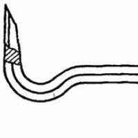 Gost scrap of ferrous metals (download) Scrap for construction gost 1405 83
 How many kilometers is the Moscow Ring Road in a circle?
 Where did the Moscow sparrows disappear: the conclusion of ornithologists Why did the sparrows disappear?
 How to make money on homemade toys?
 Creative business: making handmade toys