WEBSOR Electrical Information Territory. Territory of electrical information WEBSOR Non-removable contact connections
This standard applies to collapsible and non-collapsible electrical contact connections of buses, wires or cables (hereinafter referred to as conductors) made of copper, aluminum and its alloys, steel, aluminum-copper wires with leads of electrical devices, as well as to contact connections of conductors to each other for currents from 2, 5 A. For contact connections of electrical devices for currents less than 2.5 A, the requirements of the standard are recommended. The requirements of the standard in terms of the permissible value of electrical resistance and resistance of contact connections at through currents also apply to contact connections in the circuits of grounding and protective conductors made of steel.
The standard does not apply to electrical contact connections of special-purpose electrical devices.
| Designation: | GOST 10434-82 * |
| Russian name: | Electrical contact connections. Classification. General technical requirements |
| Status: | acting |
| Replaces: | GOST 10434-76 |
| Date of text update: | 01.10.2008 |
| Date added to the database: | 01.02.2009 |
| Effective date: | 01.01.1983 |
| Designed by: | Minmontazhspetsstroy USSR |
| Approved by: | State Standard of the USSR (03.02.1982) |
| Published: | Standards Publishing House No. 1982 Standards Publishing House No. 1994 |
STATE STANDARD SOYUZASSR
CONNECTIONS
ELECTRIC
CLASSIFICATION - GENERAL SPECIFICATIONS
GOST 10434-82
Moscow
STATE STANDARD OF THE UNION OF SSR
Date of reference 01.01.83
This standard applies to collapsible and non-collapsible electrical contact connections of tires, wires or cables (hereinafter referred to as conductors) made of copper, aluminum and its alloys, steel, aluminum-copper wires with leads from electrical devices, as well as contact connections of conductors with each other for currents from 2.5 A. connections of electrical devices for currents less than 2.5A, the requirements of the standard are recommended. The requirements of the standard in terms of the permissible value of electrical resistance and resistance of contact connections at through currents also apply to contact connections in the circuits of grounding and protective conductors made of steel.
The standard does not apply to electrical contact connections of electrical devices for special purposes.
The terms used in the standard correspond to GOST 14312-79, GOST 18311-80.
1. CLASSIFICATION
1.1. Depending on the field of application, electrical contact connections (hereinafter referred to as contact connections) are divided into classes in accordance with table. ...
Table 1
| Contact connection class |
|
| 1. Contact connections of circuits whose conductor cross-sections are selected for permissible continuous current loads (power electrical circuits, power lines, etc.) | |
| 2. Contact connections of circuits, the cross-sections of conductors of which are selected for resistance to through currents, voltage loss and deviation, mechanical strength, overload protection. Contact connections in the chains of grounding and protective conductors made of steel | |
| 3. Contact connections of circuits with electrical devices, the work of which is associated with the release of a large amount of heat (heating elements, resistors, etc.) |
Note. In the standards and technical specifications for specific types of electrical devices, classes 2 and 3 must be indicated, class 1 is not indicated.
requiring the use of means of stabilizing electrical resistance - see p. .1.7 and.
table 2
| Contact connection group |
|
| 1. All climatic versions for placement category 4.1 with an atmosphere of types II and I. Climatic versions U, UHL, TS for location category 3 and climatic versions UHL, TS for location category 4 with an atmosphere of types II and I | |
| 2. Any combination of climatic performance and placement category, other than those indicated above, for an atmosphere of types II and I. Any combination of climatic performance and placement category in an atmosphere of types III and IV |
2. TECHNICAL REQUIREMENTS
2.1. Construction requirements
2.1.1. Contact connections must be made in accordance with the requirements of this standard, standards and specifications for specific types of electrical devices according to working drawings approved in the established order.
2.1.4. Linear fittings must comply with the requirements of GOST 13276-79.
2.1.5. Non-removable contact connections should be made by welding, soldering or pressing. It is allowed to use other methods specified in standards or technical conditions for specific types of electrical devices.
Examples of making permanent contact connections are given in the appendix.
1) fasteners made of non-ferrous metals with a coefficient of linear expansion of 18× 10 -6 to 21 × 10 -6 1 / ° C;
2) Belleville springs in accordance with GOST 3057-90 or technical specifications for specific types of springs;
3) protective metal coatings of working surfaces, selected in accordance with GOST 9.303-84, taking into account the requirements of GOST 9.005-72.
It is allowed to use other types of protective coatings specified in the standards or technical conditions for specific types of electrical devices;
4) transition parts in the form of copper-aluminum plates in accordance with GOST 19357-81, copper-aluminum tips in accordance with GOST 9581-80 and hardware clamps from clad aluminum in accordance with TU 34-13-11438-89;
5) transitional parts in the form of plates and tips made of aluminum alloy with a temporary tensile strength of at least 130 MPa (hereinafter referred to as hard aluminum alloy);
6) pin tips in accordance with GOST 23598-79 made of solid aluminum alloy;
7) pin tips according to GOST 23598-79, copper-aluminum;
8) electrically conductive lubricants or other electrically conductive materials, if the possibility of their use is confirmed by test results in accordance with GOST 17441-84 and is indicated in the standards or specifications for specific types of electrical devices.
When using means 2) -8), contact connections, as a rule, must be performed using steel fasteners protected from corrosion in accordance with the requirements of GOST 9.303-84, GOST 9.005-72.
Note ... The need to apply a protective metal coating on the working surfaces of copper conductors should be specified in the standards or technical specifications for specific types of electrical devices.
(Changed edition, Amendments No. 1, 2, 3).
for contact connections of conductors with pin terminals - in table. ;
for contact connections of conductors with female leads - in table. ...
Table 3
| Conductor material | Standard clause number depending on lead material or second conductor |
|||||||||||||||||||||||||||||||||||||||||||||||||||||||||||||||||
| copper and its alloys | hard aluminum alloy | aluminum | steel |
|||||||||||||||||||||||||||||||||||||||||||||||||||||||||||||||
| Copper, aluminum-copper | Conductor material | Standard clause number depending on pin material |
||||||||||||||||||||||||||||||||||||||||||||||||||||||||||||||||
| copper or brass for rated current | steel for rated current up to 40 A |
|||||||||||||||||||||||||||||||||||||||||||||||||||||||||||||||||
| up to 630 A | above 630 A |
|||||||||||||||||||||||||||||||||||||||||||||||||||||||||||||||||
| Copper, aluminum-copper |
Note. In all cases, for pins with rated currents above 40 A, thrust nuts made of copper or brass must be used. Table 5
2.1.14. Requirements for the preparation of working surfaces of contact parts are given in the Appendix. 2.2. Electrical Requirements 2.2.1. The ratio of the initial electrical resistance of contact connections (except for contact connections with pins) to the electrical resistance of the section of the connected conductors, the length of which is equal to the length of the contact connection, should not exceed: for class 1 -1, unless otherwise specified in the standards or technical specifications for specific types of electrical devices; for class 2 -2; for class 3 -6. In contact connections of conductors with different electrical resistance, the comparison is made with a contact piece with a higher electrical resistance. 2.2.2. The initial electrical resistance of the contact connections of class 1 conductors with pin terminals should not exceed the values indicated in table. ... Table 7
Requirements for contact connections of classes 2 and 3, if necessary, are specified in the standards or technical conditions for specific types of electrical devices. | The highest permissible heating temperature,° C in installations |
||||||||||||||||||||||||||||||||||||||||||||||||||||||||||||||||
| up to 1000 V | St. 1000 V |
|||||||||||||||||||||||||||||||||||||||||||||||||||||||||||||||||
| 1. Conductors made of copper, aluminum-copper, aluminum and its alloys without protective coatings of working surfaces | According to GOST 8024-90 |
|||||||||||||||||||||||||||||||||||||||||||||||||||||||||||||||||
| 2. Conductors made of copper, aluminum copper, aluminum and its alloys with protective coatings of working surfaces with base metals | 110* |
|||||||||||||||||||||||||||||||||||||||||||||||||||||||||||||||||
| 3. Conductors made of copper and its alloys without insulation or with insulation classes V, F and N according to GOST 8865-87 with a protective coating of working surfaces with silver | 135 |
|||||||||||||||||||||||||||||||||||||||||||||||||||||||||||||||||
* Allowed for copper conductors without insulation or insulation classes B, F and N in accordance with GOST 8865-87, increase the temperature to 135 ° C, if the possibility of this is confirmed by the test results in accordance with GOST 17441-84 and is indicated in the standards or technical specifications for specific types of electrical devices.
The temperature of class 3 contact joints is set in standards or technical specifications for specific types of electrical devices, depending on the materials used, coatings, insulation class of the connected conductors and operating conditions.
(Changed edition, Amendments No. 1, 2, 3).
2.2.5. (Deleted, Amendment No. 1).
2.2.6. After the through-current mode, the contact connections should not have mechanical damage that impedes their further operation. The temperature of the contact connections in the through-current mode should not be more than 200 ° C for conductor connections made of aluminum copper, aluminum and its alloys, as well as for the connections of these conductors with copper, 300 ° C for copper conductor connections and 400 ° C for steel conductor connections.
2.2.7. The value of the permissible through current of contact connections must not be less than the permissible through currents of specific types of electrical devices specified in the standards or technical specifications for these devices.
In the absence of these data, the value of the one-second current density should correspond to 165 A / mm 2 - for copper conductors, 105 A / mm 2 - for aluminum and copper-aluminum, 90 A / mm 2 - for aluminum alloy conductors and 20 A / mm 2 - for steel conductors.
(Modified edition, Amendment No. 1).
2.3. Requirements for resistance to mechanical factors
In the absence of such instructions, contact connections subject to vibration must withstand vibration for 1 hour at a constant frequency of 40 to 50 Hz and an amplitude of 1 mm.
2.3.2. Contact joints must withstand the effects of static axial tensile loads, causing stresses, not less than:
90% of the temporary resistance to rupture of the whole conductor - for the contact connections of the wires of the power transmission line, operating in tension;
30% of the temporary resistance to rupture of the whole conductor - for non-separable contact connections that do not work in tension, as well as for connections of conductors with socket terminals, connections of unfinished wires and cables with flat terminals, complete with shaped washers.
For conductors with a cross section of up to 1.5 mm 2, it is not allowed to use a screw clamp, the end of the screw of which turns along the core.
2.3.1.-2.3.3.
2.3.4. Detachable contact connections of conductors with leads, single-bolt contact connections that may be exposed to through-current short-circuit currents, as well as dismountable contact connections subject to vibration or located in explosive areas, must be secured against self-loosening with locknuts, spring washers, Belleville springs or other methods.
(Modified edition, Amendment No. 2).
2.4. Reliability requirements
2.4.1. To assess the reliability of contact connections, a gamma-percentage resource is established, unless otherwise established in the standards or technical specifications for specific types of electrical devices.
The lower value of the gamma-percent resource should ensure the operation of electrical devices in accordance with the reliability requirements established in the standards or technical conditions for these electrical devices.
(Modified edition, Amendment No. 1).
2.5. Safety requirements
2.5.1. Contact connections in terms of safety requirements must comply with GOST 12.2.007.0-75and ensure the operating conditions established by the "Rules for the technical operation of consumer installations" and "Safety rules for the operation of electrical installations of consumers", approved by the State Energy Supervision Service on April 12, 1969.
2.5.2. Contact connections in terms of fire safety requirements must comply GOST12.1.004-91, which is ensured by meeting the requirementsGOST 10434-82 .
(Introduced additionally, Amendment No. 3).
ANNEX 1
Reference
NON-DISCONTINUOUS CONTACT CONNECTIONS

a -welding or soldering; b- with a pinned output by welding; v- welding through a transition copper-aluminum plate; G - connection of cores of wires (cables) through a connecting sleeve by crimping; d- connection of a core of a wire (cable) with a cable tip by crimping (welding, soldering); e - connection of wire cores in oval connectors
1 - flat terminal (bus); 2 - tire; 3 - pin terminal; 4 5- wire (cable); 6 - connecting sleeve; 7 - cable lug; 8 - oval connector
APPENDIX 2
Reference
FLEXIBLE CONTACT CONNECTIONS
Detachable contact connections of conductors with flat leads without means of stabilizing electrical resistance

a- with a lock nut; b- a spring washer; v- single-wire (multi-wire) conductor of a wire (cable) cross-section. up to 10 mm 2 with bending into a ring; G- single-wire (multi-wire) conductor of a wire (cable) section. up to 10mm 2 without bending into a ring.
1 - flat terminal (bus); 2 - bus (cable lug); 3, 4, 5 - steel washer, bolt and nut; 6- spring washer; 7 - screw; 8 - shaped washer (washer-star); 9 - wire (cable); 10 - shaped washer (arched washer)
Crap. one
Detachable contact connections of conductors with flat leads with means of stabilization of electrical resistance

a- fasteners made of non-ferrous metal with a lock nut; b- fasteners made of non-ferrous metal with a spring washer; v- steel fasteners with a Belleville spring; G- steel fasteners with protective metal coatings of the working surfaces with a lock nut (spring washer); d- steel fasteners through a copper-aluminum transition plate with a lock nut (spring washer); e - steel fasteners through a hard aluminum adapter plate with a lock nut (lock washer).
1 - flat terminal (bus); 2 -bus (cable lug); 3 - 5 - washer, bolt, nut from non-ferrous metal; 6 - spring washer; 7 - steel nut; 8 -steel bolt; 9 - Belleville spring; 10 - steel washer (enlarged washer); 11 - steel washer; 12 - flat terminal (bus) with a protective metal coating of the working surface; 13 - bus (cable lug) with a protective metal coating on the working surface; 14- copper-aluminum plate; 15 - hard aluminum alloy plate
Crap. 2
Dismountable contact connections of conductors with pin terminals without means and with means of stabilizing electrical resistance

a -conductor made of copper, hard aluminum alloy or aluminum with a protective metal coating on the working surface; b, c, G- aluminum conductor; d - aluminum conductor through the copper-aluminum adapter plate; e- single-wire (multi-wire) conductor of a wire of a cable cross-section. 10mm 2 with bending into a ring.
1- pin terminal made of copper or brass; 2 - nut made of copper or brass; 3 - bus (cable lug) made of copper, hard aluminum alloy or aluminum with a protective metal coating of working surfaces; 4 - steel nut; 5 - pin-type copper lead; 6 - steel washer; 7 - aluminum bus (cable lug); 8 - pin brass lead; 9 - pin steel lead; 10 - Belleville spring; 11 - copper-aluminum plate; 12 - wire (cable); 13 - spring washer; 14 - shaped washer (star washer)
Crap. 3
Detachable contact connections of conductors with female leads

a, b- single-wire (multi-wire, fused into a monolith) conductor; v- stranded conductor, terminated with a cable lug.
1 - type-setting clip; 2 -wire (cable); 3 - nested output; 4 - cable lug pin
Crap. 4
APPENDIX 3
REQUIREMENTS FOR PREPARATION OF WORKING SURFACES OF CONTACT PARTS
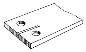
1. Contact parts with two or more bolt holes in the transverse row are recommended to be made with longitudinal cuts, as shown in the drawing.
2. Working surfaces of contact parts of collapsible contact connections and non-separable contact connections with linear fittings immediately before assembly should be prepared:
copper uncoated and copper-alumina - cleaned.
When stripping aluminum-copper wires, the copper sheath should not be damaged;
aluminum and aluminum alloys - cleaned and lubricated with neutral grease (KVZ petroleum jelly according to GOST 15975-70, CIATIM-221 according to GOST 9433-80 or other greases with similar properties).
working surfaces with protective metal coatings - washed with an organic solvent.
(Modified edition, Amendment No. 3).
3. Working surfaces of copper contact parts connected by crimping must be cleaned, unless otherwise specified in the standards or technical specifications for specific types of electrical devices.
Working surfaces of aluminum contact parts must be cleaned and lubricated with quartz-vaseline paste or other lubricants, pastes and compounds with similar properties.
4. The surfaces of the contact parts to be welded or brazed must be pre-cleaned, degreased or pickled.
5. The location and size of bolt holes in the contact details of collapsible contact connections are recommended to be taken in accordance with GOST 21242-75.
By agreement with the consumer, it is allowed to make oval holes.
Standards> GOST, SNiP, SP, TU
GOST 10434-82. Electrical contact connections. Classification. General specifications
(with amendments N 1, 2, 3)
GOST 10434-82
Group E78
INTERSTATE STANDARD
ELECTRICAL CONTACT CONNECTIONS
Classification. General technical requirements
Electric contact connections. Classification. General technical requirements
ISS 29.120.20
Date of introduction 1983-01-01
This standard applies to collapsible and non-collapsible electrical contact connections of buses, wires or cables (hereinafter referred to as conductors) made of copper, aluminum and its alloys, steel, aluminum-copper wires with leads of electrical devices, as well as to contact connections of conductors to each other for currents from 2, 5 A. For contact connections of electrical devices for currents less than 2.5 A, the requirements of the standard are recommended. The requirements of the standard in terms of the permissible value of electrical resistance and resistance of contact connections at through currents also apply to contact connections in the circuits of grounding and protective conductors made of steel.
The standard does not apply to electrical contact connections of special-purpose electrical devices.
The terms used in the standard correspond to GOST 14312, GOST 18311.
1. CLASSIFICATION
1.1. Depending on the field of application, electrical contact connections (hereinafter referred to as contact connections) are divided into classes in accordance with Table 1.
Table 1
Contact connection scope |
Contact connection class |
1. Contact connections of circuits whose conductor cross-sections are selected for permissible continuous current loads (power electrical circuits, power lines, etc.) |
|
2. Contact connections of circuits, the cross-sections of conductors of which are selected for resistance to through currents, voltage loss and deviation, mechanical strength, overload protection. Contact connections in the chains of grounding and protective conductors made of steel |
|
3. Contact connections of circuits with electrical devices, the work of which is associated with the release of a large amount of heat (heating elements, resistors, etc.) |
|
Note. In the standards and specifications for electrical devices of specific types, classes 2 and 3 must be indicated, class 1 is not indicated. |
|
1.2. Depending on the climatic version and the category of placement of electrical devices in accordance with GOST 15150, contact connections are divided into groups in accordance with Table 2.
table 2
1. All climatic versions for placement category 4.1 with an atmosphere of types II and I.
|
|
2. Any combination of climatic performance and placement category, other than those indicated above, for an atmosphere of types II and I.
|
|
1.3. By design, contact connections are subdivided into non-collapsible and collapsible.
1.4. Depending on the material of the connected conductors and the group of contact connections according to clause 1.2, collapsible contact connections are divided into:
- that do not require the use of means of stabilizing electrical resistance - see clauses 2.1.6 and 2.1.8;
- requiring the use of means of stabilizing electrical resistance - see clauses 2.1.7 and 2.1.8.
2. TECHNICAL REQUIREMENTS
2.1. Construction requirements
2.1.1. Contact connections must be carried out in accordance with the requirements of this standard, standards and specifications for electrical devices of specific types according to working drawings, approved in the prescribed manner.
2.1.2. The conclusions of electrical devices must comply with the requirements of GOST 24753.
2.1.3. Contact screw clamps must comply with the requirements of GOST 25034, typesetting clamps must comply with the requirements of GOST 19132.
2.1.4. Linear fittings must comply with the requirements of GOST 13276.
2.1.5. Permanent contact connections must be welded, soldered or crimped. It is allowed to use other methods specified in standards or technical specifications for specific types of electrical devices.
Examples of making non-separable contact connections are given in Appendix 1.
2.1.6. Dismountable contact connections that do not require the use of means of stabilizing electrical resistance must be made using steel fasteners protected from corrosion in accordance with the requirements of GOST 9.303, GOST 9.005.
(Modified edition, Amendment N 2).
2.1.7. Detachable contact connections requiring the use of means of stabilizing electrical resistance must be performed using either individually or in combination with the following means:
1) fasteners made of non-ferrous metals with a coefficient of linear expansion from 18 · 10 to 21 · 10 1 / ° С;
2) Belleville springs in accordance with GOST 3057 or technical specifications for specific types of springs;
3) protective metal coatings of working surfaces, selected in accordance with GOST 9.303, taking into account the requirements of GOST 9.005.
It is allowed to use other types of protective coatings specified in the standards or technical specifications for specific types of electrical devices;
4) transition parts in the form of copper-aluminum plates in accordance with GOST 19357, copper-aluminum lugs in accordance with GOST 9581 and hardware clamps made of clad aluminum in accordance with TU 34-13-11438 *;
5) transitional parts in the form of plates and tips made of aluminum alloy with a ultimate tensile strength of at least 130 MPa (hereinafter referred to as hard aluminum alloy);
6) pin lugs in accordance with GOST 23598, made of hard aluminum alloy;
7) pin lugs in accordance with GOST 23598, copper-aluminum;
8) electrically conductive lubricants or other electrically conductive materials, if the possibility of their use is confirmed by test results in accordance with GOST 17441 and is indicated in the standards or technical conditions for specific types of electrical devices.
When using means 2) - 8), contact connections, as a rule, should be performed using steel fasteners protected from corrosion in accordance with the requirements of GOST 9.303, GOST 9.005.
Note. The need to apply a protective metal coating on the working surfaces of copper conductors should be specified in the standards or technical specifications for specific types of electrical devices.
(Changed edition, Rev. N 1, 2, 3).
2.1.8. Collapsible contact connections, depending on the group according to clause 1.2 and the material of the connected conductors and terminals of electrical devices, must be performed in accordance with the requirements of the standard, indicated:
- for contact connections of conductors with flat terminals, as well as contact connections of conductors with each other - in table 3;
- for contact connections of conductors with pin terminals - in table 4;
- for contact connections of conductors with female leads - in table 5.
Table 3
Contact group
|
Material |
Standard clause number depending on lead material or second conductor |
|||
copper and its alloys |
hard aluminum alloy |
aluminum |
steel |
||
Copper, aluminum-copper |
2.1.6 |
2.1.7
|
2.1.6 |
||
Solid aluminum alloy |
|||||
Aluminum |
2.1.7 1) or 2), or 3), or 4), or 5), or 8) |
||||
Copper, aluminum-copper |
2.1.6 |
2.1.7*
|
2.1.7
|
2.1.6 |
|
Solid aluminum alloy |
2.1.7*
|
2.1.6 |
2.1.7
|
2.1.7
|
|
Aluminum |
2.1.7
|
2.1.7
|
|||
* Contact connections of electrical devices of climatic modifications U, UHL of placement categories 1 and 2 are allowed to be made according to clause 2.1.6. |
|||||
Table 4
Contact connection group |
Material |
Standard clause number depending on pin material |
||
copper or brass for rated current |
steel for rated current up to 40 A |
|||
up to 630 A |
St. 630 A |
|||
Copper, aluminum-copper |
2.1.6 |
|||
Solid aluminum alloy |
||||
Aluminum |
2.1.7
|
2.1.7
|
2.1.7
|
|
Copper, aluminum-copper |
2.1.6 |
|||
Solid aluminum alloy |
2.1.7
|
2.1.7*
|
2.1.7
|
|
Aluminum |
2.1.7 4) or 5) and 3) |
|||
* Contact connections of electrical devices of climatic modifications U, UHL of placement categories 1 and 2 are allowed to be made according to clause 2.1.6.
|
||||
Table 5
Contact connection group |
Conductor material |
Standard clause number depending on the type of core |
|
single-wire |
multi-wire |
||
Copper |
Direct connection |
||
Alumomed |
|||
Aluminum |
Direct connection * or 2.1.7 6) or 7) ** |
||
Copper |
Direct connection * or 2.1.6 *** |
2.1.6*** |
|
Alumomed |
|||
Aluminum |
2.1.7 7) or 6) and 3) |
||
* The possibility of direct connection must be specified in the standards or technical specifications for specific types of electrical devices.
|
|||
Contact connections in accordance with the climatic design and the category of placement of electrical devices, determined in accordance with GOST 15150 and GOST 15543, must withstand the influence of climatic factors of the external environment specified in GOST 15150, GOST 15543, GOST 15963, GOST 16350, GOST 17412 or in standards and technical conditions for specific types of electrical devices.
It is allowed, upon agreement with the consumer, to use contact connections that differ from those indicated in Table 3-5.
Examples of making collapsible contact connections are given in Appendix 2.
(Modified edition, Amendments N 1, 3).
2.1.9. Contact joints of plates made of hard aluminum alloy and the aluminum part of copper-aluminum plates with aluminum conductors (leads) must be performed by welding or soldering, and the connections of lugs made of hard aluminum alloy and the aluminum part of copper-aluminum lugs with aluminum conductors of wires and cables must be welded or crimping.
2.1.10. Detachable contact connections of single-wire conductors of wires and cables with flat or pin terminals should be performed:
- lived with a cross section of up to 16 mm sq. - after termination with tips according to GOST 7386 or directly: by forming into a ring or without it, with protection in both cases from extrusion by shaped washers or by other methods;
- lived with a section of 25 mm sq. and more - after termination with ferrules in accordance with GOST 7386, GOST 7387, GOST 9581 or by forming the end of the conductor into a flat clamping part with a bolt hole.
2.1.11 Dismountable contact connections of stranded conductors of wires and cables with flat or pin leads should be performed:
- lived with a cross section of up to 10 mm sq. - after termination with tips according to GOST 7386, GOST 9688, GOST 22002.1, GOST 22002.2-GOST 22002.4, GOST 22002.6, GOST 22002.7-GOST 22002.11, GOST 22002.14 or directly: by forming into a ring or without it, with protection in both cases from extrusion by shaped washers or in other ways;
- lived with a section of 16 mm sq. and more - after termination with ferrules in accordance with GOST 7386, GOST 7387, GOST 9581, GOST 22002.1, GOST 22002.2, GOST 22002.6, GOST 22002.7.
(Modified edition, Rev. N 1, 2).
2.1.12. It is recommended to connect no more than two conductors to each bolt (screw) of a flat terminal or to a pin terminal, unless otherwise specified in the standards or technical specifications for specific types of electrical devices.
2.1.13. In collapsible contact joints, fasteners of strength classes according to and, indicated in Table 6, must be used. It is recommended to use screws in contact connections with a cylindrical or hexagonal head.
Table 6
(Modified edition, Amendment N 3).
2.1.14. Requirements for the preparation of working surfaces of contact parts are given in Appendix 3.
2.2. Electrical Requirements
2.2.1. The ratio of the initial electrical resistance of contact connections (except for contact connections with pin terminals) to the electrical resistance of the section of the connected conductors, the length of which is equal to the length of the contact connection, should not exceed:
- for class 1-1, unless otherwise specified in the standards or technical specifications for specific types of electrical devices;
- for class 2-2;
- for class 3-6.
In contact connections of conductors with different electrical resistance, comparison is made with a contact piece with a high electrical resistance.
2.2.2. The initial electrical resistance of the contact connections of class 1 conductors with pins should not exceed the values indicated in table 7.
Table 7
Pin diameter, mm |
||||||||||||||||
Initial electrical resistance of contact connections with copper and brass leads according to GOST 21242, μOhm |
||||||||||||||||
Requirements for contact connections of classes 2 and 3, if necessary, are specified in standards or technical specifications for specific types of electrical devices.
2.2.3. The electrical resistance of contact joints (except for welded and soldered) that have passed the test for compliance with the requirements of standards and other technical documentation according to the method specified in GOST 17441 should not exceed the initial value by more than 1.5 times. The electrical resistance of welded and soldered contact joints must remain unchanged. The need for the mandatory use of torque wrenches should be indicated in the standards or technical specifications for specific types of electrical devices.
(Modified edition, Amendment N 3).
2.2.4. When the rated (long-term allowable) current flows, the maximum allowable temperature of contact connections of classes 1 and 2 should not exceed the values specified in table 8. In this case, the current loads of the conductors are taken according to the Rules for the Installation of Electrical Installations, approved by the State Energy Supervision Service on 04/12/1969, according to the standards or specifications for specific types of electrical devices.
Table 8
Characteristics of the connected conductors |
The highest permissible heating temperature, ° C, in installations |
|
up to 1000 V |
St. 1000 V |
|
1. Conductors made of copper, aluminum-copper, aluminum and its alloys without protective coatings of working surfaces |
According to GOST 8024 |
|
2. Conductors made of copper, aluminum copper, aluminum and its alloys with protective coatings of working surfaces with base metals |
110* |
|
3. Conductors made of copper and its alloys without insulation or with insulation of classes B, F and H in accordance with GOST 8865 with a protective coating of working surfaces with silver |
||
* It is allowed for copper conductors without insulation or with insulation of classes B, F and H according to GOST 8865 to increase the temperature to 135 ° C, if the possibility of this is confirmed by the test results according to GOST 17441 and is indicated in the standards or technical specifications for specific types of electrical devices. |
||
The temperature of the contact connections of class 3 is established in the standards or technical conditions for electrical devices of specific types, depending on the materials used, coatings, insulation class of the connected conductors and operating conditions.
(Changed edition, Rev. N 1, 2, 3).
2.2.5. (Deleted, Rev. N 1).
2.2.6. After the through-current mode, the contact connections should not have mechanical damage that impedes their further operation. The temperature of the contact joints in the through-current mode should not be more than 200 ° С for the connections of conductors made of aluminum copper, aluminum and its alloys, as well as for the connections of these conductors with copper ones, 300 ° С for the connections of copper conductors and 400 ° С for the connections of steel conductors.
2.2.7. The value of the permissible through-current of contact connections must be not less than the permissible through-currents of specific types of electrical devices specified in the standards or technical specifications for these devices.
In the absence of these data, the value of the one-second current density should correspond to 165 A / mm - for copper conductors, 105 A / mm - for aluminum and aluminum-copper, 90 A / mm - for aluminum alloy conductors and 20 A / mm - for steel conductors.
2.3. Requirements for resistance to mechanical factors
2.3.1. Contact connections must withstand the impact of mechanical factors of the external environment according to the group of operating conditions in accordance with GOST 17516, which must be indicated in the standards or technical conditions for specific types of electrical devices.
In the absence of such instructions, contact connections subject to vibration shall withstand vibration for 1 hour at a constant frequency of 40 to 50 Hz and an amplitude of 1 mm.
2.3.2. Contact connections must withstand the effects of static axial tensile loads, causing stresses, not less than:
- 90% of the ultimate tensile strength of the whole conductor - for the contact connections of the wires of the power transmission line operating in tension;
- 30% of the ultimate tensile strength of the whole conductor - for non-separable contact connections that do not work in tension, as well as for connections of conductors with socket leads, connections of unfinished wires and cables with flat leads, complete with shaped washers.
2.3.3. It is recommended to tighten the bolts with torque indicator wrenches, for example, DK-25, screws - with calibrated screwdrivers. The torques are indicated in Appendix 4.
For conductors up to 1.5 mm2 it is not allowed to use a screw clamp, the end of the screw of which turns along the core.
2.3.1-2.3.3. (Modified edition, Amendment N 1).
2.3.4. Detachable contact connections of conductors with leads, single-bolt contact connections that can be exposed to through short-circuit currents, as well as demountable contact connections subject to vibration or located in explosive areas, must be secured against self-loosening by locknuts, spring washers, Belleville springs or other methods.
(Modified edition, Amendment N 2).
2.4. Reliability requirements
2.4.1. To assess the reliability of contact connections, a gamma-percentage resource is established, unless otherwise specified in the standards or technical specifications for specific types of electrical devices.
The lower value of the gamma-percentage resource should ensure the operation of electrical devices in accordance with the reliability requirements established in the standards or technical specifications for these electrical devices.
(Modified edition, Amendment N 1).
2.5. Safety requirements
2.5.1. Contact connections in terms of safety requirements must comply with GOST 12.2.007.0 and ensure the operating conditions established by the Rules for the technical operation of consumer installations and the Rules on labor protection during the operation of electrical installations.
STATE STANDARD OF THE UNION OF SSR
CONNECTIONS CONTACT
ELECTRIC
CLASSIFICATION. GENERAL TECHNICAL REQUIREMENTS
GOST 10434-82
Moscow
STATE STANDARD OF THE UNION OF SSR
Date of reference 01.01.83
This standard applies to collapsible and non-collapsible electrical contact connections of buses, wires or cables (hereinafter referred to as conductors) made of copper, aluminum and its alloys, steel, aluminum-copper wires with leads of electrical devices, as well as to contact connections of conductors to each other for currents from 2, 5 A. For contact connections of electrical devices for currents less than 2.5 A, the requirements of the standard are recommended. The requirements of the standard in terms of the permissible value of electrical resistance and resistance of contact connections at through currents also apply to contact connections in the circuits of grounding and protective conductors made of steel.
The standard does not apply to electrical contact connections of special-purpose electrical devices.
The terms used in the standard correspond to GOST 14312-79, GOST 18311-80.
1. CLASSIFICATION
1.1. Depending on the field of application, electrical contact connections (hereinafter referred to as contact connections) are divided into classes in accordance with table. ...
Table 1
|
Contact connection class |
|
|
1. Contact connections of circuits whose conductor cross-sections are selected for permissible continuous current loads (power electrical circuits, power lines, etc.) |
|
|
2. Contact connections of circuits, the cross-sections of conductors of which are selected for resistance to through currents, voltage loss and deviation, mechanical strength, overload protection. Contact connections in the chains of grounding and protective conductors made of steel |
|
|
3. Contact connections of circuits with electrical devices, the work of which is associated with the release of a large amount of heat (heating elements, resistors, etc.) |
Note. In the standards and specifications for specific types of electrical devices, classes 2 and 3 must be indicated, class 1 is not indicated.
requiring the use of means of stabilizing electrical resistance - see p. .1.7 and.
table 2
|
Contact connection group |
|
|
1. All climatic versions for placement category 4.1 with an atmosphere of types II and I. Climatic versions U, UHL, TS for location category 3 and climatic versions UHL, TS for location category 4 with an atmosphere of types II and I |
|
|
2. Any combination of climatic performance and placement category, other than those indicated above, for an atmosphere of types II and I. Any combination of climatic performance and placement category in an atmosphere of types III and IV |
2. TECHNICAL REQUIREMENTS
2.1. Construction requirements
2.1.1. Contact connections must be carried out in accordance with the requirements of this standard, standards and technical specifications for specific types of electrical devices according to working drawings approved in the prescribed manner.
2.1.4. Linear fittings must comply with the requirements of GOST 13276-79.
2.1.5. Permanent contact connections must be welded, soldered or crimped. It is allowed to use other methods specified in standards or technical specifications for specific types of electrical devices.
Examples of non-separable contact connections are given in the appendix.
1) fasteners made of non-ferrous metals with a coefficient of linear expansion of 18× 10 -6 to 21 × 10 -6 1 / ° C;
2) Belleville springs in accordance with GOST 3057-90 or technical specifications for specific types of springs;
3) protective metal coatings of working surfaces, selected in accordance with GOST 9.303-84, taking into account the requirements of GOST 9.005-72.
It is allowed to use other types of protective coatings specified in standards or technical specifications for specific types of electrical devices;
4) transitional parts in the form of copper-aluminum plates in accordance with GOST 19357-81, copper-aluminum lugs in accordance with GOST 9581-80 and hardware clamps made of clad aluminum in accordance with TU 34-13-11438-89;
5) transitional parts in the form of plates and tips made of aluminum alloy with a ultimate tensile strength of at least 130 MPa (hereinafter referred to as hard aluminum alloy);
6) pin lugs in accordance with GOST 23598-79 made of hard aluminum alloy;
7) pin lugs in accordance with GOST 23598-79, copper-aluminum;
8) electrically conductive lubricants or other electrically conductive materials, if the possibility of their use is confirmed by test results in accordance with GOST 17441-84 and is indicated in the standards or technical specifications for specific types of electrical devices.
When using means 2) -8), contact connections, as a rule, should be performed using steel fasteners protected from corrosion in accordance with the requirements of GOST 9.303-84, GOST 9.005-72.
Note ... The need to apply a protective metal coating on the working surfaces of copper conductors should be specified in the standards or technical specifications for specific types of electrical devices.
(Modified edition, Amendments No. 1, 2, 3).
for contact connections of conductors with pin terminals - in table. ;
for contact connections of conductors with female leads - in table. ...
Table 3
|
Conductor material |
Standard clause number depending on lead material or second conductor |
|||||||||||||||||||||||||||||||||||||||||||||||||||||||||||||||||
|
copper and its alloys |
hard aluminum alloy |
aluminum |
steel |
|||||||||||||||||||||||||||||||||||||||||||||||||||||||||||||||
|
Copper, aluminum-copper |
Conductor material |
Standard clause number depending on pin material |
||||||||||||||||||||||||||||||||||||||||||||||||||||||||||||||||
|
copper or brass for rated current |
steel for rated current up to 40 A |
|||||||||||||||||||||||||||||||||||||||||||||||||||||||||||||||||
|
up to 630 A |
above 630 A |
|||||||||||||||||||||||||||||||||||||||||||||||||||||||||||||||||
|
Copper, aluminum-copper |
Note. In all cases, copper or brass thrust nuts must be used for pins with rated currents above 40 A. Table 5
2.1.14. Requirements for the preparation of working surfaces of contact parts are given in the appendix. 2.2. Electrical Requirements 2.2.1. The ratio of the initial electrical resistance of contact connections (except for contact connections with pin terminals) to the electrical resistance of the section of the connected conductors, the length of which is equal to the length of the contact connection, should not exceed: for class 1 - 1, unless otherwise specified in the standards or technical specifications for specific types of electrical devices; for class 2 - 2; for class 3 - 6. In contact connections of conductors with different electrical resistance, comparison is made with a contact piece with a higher electrical resistance. 2.2.2. The initial electrical resistance of the contact connections of class 1 conductors with pin leads should not exceed the values indicated in table. ... Table 7
Requirements for contact connections of classes 2 and 3, if necessary, are specified in standards or technical specifications for specific types of electrical devices. |
The highest permissible heating temperature,° С in installations |
||||||||||||||||||||||||||||||||||||||||||||||||||||||||||||||||
|
up to 1000 V |
St. 1000 V |
|||||||||||||||||||||||||||||||||||||||||||||||||||||||||||||||||
|
1. Conductors made of copper, aluminum-copper, aluminum and its alloys without protective coatings of working surfaces |
According to GOST 8024-90 |
|||||||||||||||||||||||||||||||||||||||||||||||||||||||||||||||||
|
2. Conductors made of copper, aluminum copper, aluminum and its alloys with protective coatings of working surfaces with base metals |
110* |
|||||||||||||||||||||||||||||||||||||||||||||||||||||||||||||||||
|
3. Conductors made of copper and its alloys without insulation or with insulation classes V, Fand N according to GOST 8865-87 with a protective coating of working surfaces with silver |
||||||||||||||||||||||||||||||||||||||||||||||||||||||||||||||||||
* Allowed for copper conductors without insulation or with insulation classes B, F and N in accordance with GOST 8865-87, increase the temperature to 135 ° C, if the possibility of this is confirmed by the test results in accordance with GOST 17441-84 and is indicated in the standards or technical conditions for specific types of electrical devices.
The temperature of class 3 contact connections is set in standards or technical conditions for specific types of electrical devices, depending on the materials used, coatings, insulation class of the connected conductors and operating conditions.
(Modified edition, Amendments No. 1, 2, 3).
2.2.5. (Deleted, Amendment No. 1).
2.2.6. After the through-current mode, the contact connections should not have mechanical damage that impedes their further operation. The temperature of the contact joints in the through-current mode should not be more than 200 ° С for the connections of conductors made of aluminum copper, aluminum and its alloys, as well as for the connections of these conductors with copper ones, 300 ° С for the connections of copper conductors and 400 ° С for the connections of steel conductors.
2.2.7. The value of the permissible through-current of contact connections must be no less than the permissible through-currents of specific types of electrical devices specified in the standards or technical specifications for these devices.
In the absence of these data, the value of the one-second current density should correspond to 165 A / mm 2 - for copper conductors, 105 A / mm 2 - for aluminum and copper-aluminum, 90 A / mm 2 - for aluminum alloy conductors and 20 A / mm 2 - for steel conductors.
(Modified edition, Amendment No. 1).
2.3. Requirements for resistance to mechanical factors
In the absence of such instructions, contact connections subject to vibration shall withstand vibration for 1 hour at a constant frequency of 40 to 50 Hz and an amplitude of 1 mm.
2.3.2. Contact connections must withstand the effects of static axial tensile loads, causing stresses, not less than:
90% of the ultimate tensile strength of the whole conductor - for the contact connections of the wires of the power transmission line operating in tension;
30% of the ultimate tensile strength of the whole conductor - for non-separable contact connections that do not work in tension, as well as for connections of conductors with socket leads, connections of unfinished wires and cables with flat leads, complete with shaped washers.
For conductors with a cross-section of up to 1.5 mm 2, it is not allowed to use a screw clamp, the end of the screw of which rotates along the core.
2.3.1.-2.3.3.
2.3.4. Detachable contact connections of conductors with leads, single-bolt contact connections that can be exposed to through short-circuit currents, as well as demountable contact connections subject to vibration or located in explosive areas, must be secured against self-loosening by locknuts, spring washers, Belleville springs or other methods.
(Modified edition, Amendment No. 2).
2.4. Reliability requirements
2.4.1. To assess the reliability of contact connections, a gamma-percentage resource is established, unless otherwise specified in the standards or technical specifications for specific types of electrical devices.
The lower value of the gamma-percentage resource should ensure the operation of electrical devices in accordance with the reliability requirements established in the standards or technical specifications for these electrical devices.
(Modified edition, Amendment No. 1).
2.5. Safety requirements
2.5.1. Contact connections in terms of safety requirements must comply with GOST 12.2.007.0-75 and ensure the operating conditions established by the "Rules for the technical operation of consumer installations" and "Safety regulations for the operation of electrical installations of consumers" approved by the State Energy Supervision Service on April 12, 1969.
2.5.2. Contact connections in terms of fire safety requirements must comply with GOST 12.1.004-91 , which is ensured by meeting the requirements GOST 10434-82 .
(Introduced additionally, Amendment No. 3).
ANNEX 1
Reference
NON-DISCONTINUOUS CONTACT CONNECTIONS

a -welding or soldering; b- with a pin output by welding; v- welding through a transition copper-aluminum plate; G - connection of cores of wires (cables) through a connecting sleeve by crimping; d- connection of a core of a wire (cable) with a cable lug by crimping (welding, soldering); e - connection of wire cores in oval connectors
1 - flat terminal (bus); 2 - tire; 3 - pin terminal; 4 - copper-aluminum plate; 5 - wire (cable); 6 - connecting sleeve; 7 - cable lug; 8 - oval connector
APPENDIX 2
Reference
FLEXIBLE CONTACT CONNECTIONS
Detachable contact connections of conductors with flat leads without means of stabilizing electrical resistance

a- with a lock nut; b- with a spring washer; v- single-wire (multi-wire) conductor of a wire (cable) cross-section. up to 10 mm 2 with bending into a ring; G- single-wire (multi-wire) conductor of a wire (cable) cross-section. up to 10mm 2 without bending into a ring.
1 - flat terminal (bus); 2 - bus (cable lug); 3, 4, 5 - steel washer, bolt and nut; 6 - spring washer; 7 - screw; 8 - shaped washer (washer-star); 9 - wire (cable); 10 - shaped washer (arched washer)
Crap. one
Detachable contact connections of conductors with flat leads with means for stabilizing electrical resistance

a- fasteners made of non-ferrous metal with a lock nut; b- fasteners made of non-ferrous metal with a spring washer; v- steel fasteners with a Belleville spring; G- steel fasteners with protective metal coatings of working surfaces with a lock nut (spring washer); d- steel fasteners through a copper-aluminum transition plate with a lock nut (spring washer); e - steel fasteners through a hard aluminum adapter plate with a lock nut (lock washer).
1 - flat terminal (bus); 2 - bus (cable lug); 3 - 5 - washer, bolt, nut made of non-ferrous metal; 6 - spring washer; 7 - steel nut; 8 - steel bolt; 9 - Belleville spring; 10 - steel washer (enlarged washer); 11 - steel washer; 12 - flat terminal (bus) with a protective metal coating of the working surface; 13 - bus (cable lug) with a protective metal coating on the working surface; 14 - copper-aluminum plate; 15 - hard aluminum alloy plate
Crap. 2
Dismountable contact connections of conductors with pin terminals without means and with means of stabilizing electrical resistance

a -conductor made of copper, hard aluminum alloy or aluminum with a protective metal coating on the working surface; b, c, G- aluminum conductor; d - aluminum conductor through the copper-aluminum adapter plate; e- single-wire (multi-wire) conductor of a wire of a cable cross-section. 10mm 2 with bending into a ring.
1- pin terminal made of copper or brass; 2 - nut made of copper or brass; 3 - busbar (cable lug) made of copper, hard aluminum alloy or aluminum with a protective metal coating on the working surfaces; 4 - steel nut; 5 - pin copper lead; 6 - steel washer; 7 - aluminum bus (cable lug); 8 - pin brass lead; 9 - pin steel lead; 10 - Belleville spring; 11 - copper-aluminum plate; 12 - wire (cable); 13 - spring washer; 14 - shaped washer (star washer)
Crap. 3
Dismountable contact connections of conductors with female leads

a, b- single-wire (multi-wire, fused into a monolith) conductor; v- stranded conductor terminated with a cable lug.
1 - type-setting clip; 2 - wire (cable); 3 - nested output; 4 - cable lug pin
Crap. 4
APPENDIX 3
REQUIREMENTS FOR THE PREPARATION OF WORKING SURFACES OF CONTACT PARTS

1. Contact parts with two or more bolt holes in the transverse row are recommended to be made with longitudinal cuts, as shown in the drawing.
2. The working surfaces of the contact parts of collapsible contact connections and non-separable contact connections with linear reinforcement immediately before assembly must be prepared:
uncoated copper and copper-alumina - brushed.
When stripping aluminum-copper wires, the copper sheath should not be damaged;
aluminum and aluminum alloys - cleaned and lubricated with neutral grease (KVZ petroleum jelly in accordance with GOST 15975-70, TsIATIM-221 in accordance with GOST 9433-80 or other greases with similar properties).
working surfaces with protective metal coatings - washed with an organic solvent.
(Modified edition, Amendment No. 3).
3. The working surfaces of the copper contact parts connected by crimping must be cleaned, unless otherwise specified in the standards or technical specifications for specific types of electrical devices.
The working surfaces of aluminum contact parts must be cleaned and lubricated with quartz-vaseline paste or other lubricants, pastes and compounds with similar properties.
4. The surfaces of the contact parts to be welded or brazed must be pre-cleaned, degreased or etched.
5. The location and size of bolt holes in the contact details of collapsible contact connections are recommended to be taken in accordance with GOST 21242-75.
By agreement with the consumer, it is allowed to make oval holes.
(Introduced additionally, Amendment No. 2).
APPENDIX 4
TORQUES
Table 9
|
Thread diameter, mm |
Torque, N× m, for bolted connection |
||||||||||||||||||||||||||||||||||||||||||||||||||||||||||||||||||||||||||||||||||||||||||||||||||||||||||||||||||||||||||||||||||||||||||||||||||||||||||||||||||||||||||||||||||||||||||||||||||||||||||||||||||||||||||||||||||||||||||||||||||||||||||||||||||||||||||||||||||||||||||||||||||||||||||||||||||||||||||||||||||||||||||||||||||||||||||||||||||||||||||||||||||||||||||||||||||||||||||||||||||||||||||||||||||||||||||||||||||||||||||||
|
slotted head (screws) |
hex head |
||||||||||||||||||||||||||||||||||||||||||||||||||||||||||||||||||||||||||||||||||||||||||||||||||||||||||||||||||||||||||||||||||||||||||||||||||||||||||||||||||||||||||||||||||||||||||||||||||||||||||||||||||||||||||||||||||||||||||||||||||||||||||||||||||||||||||||||||||||||||||||||||||||||||||||||||||||||||||||||||||||||||||||||||||||||||||||||||||||||||||||||||||||||||||||||||||||||||||||||||||||||||||||||||||||||||||||||||||||||||||||
|
0,5+0,1 |
|||||||||||||||||||||||||||||||||||||||||||||||||||||||||||||||||||||||||||||||||||||||||||||||||||||||||||||||||||||||||||||||||||||||||||||||||||||||||||||||||||||||||||||||||||||||||||||||||||||||||||||||||||||||||||||||||||||||||||||||||||||||||||||||||||||||||||||||||||||||||||||||||||||||||||||||||||||||||||||||||||||||||||||||||||||||||||||||||||||||||||||||||||||||||||||||||||||||||||||||||||||||||||||||||||||||||||||||||||||||||||||
|
M3.5 |
0.8 ± 0.2 |
||||||||||||||||||||||||||||||||||||||||||||||||||||||||||||||||||||||||||||||||||||||||||||||||||||||||||||||||||||||||||||||||||||||||||||||||||||||||||||||||||||||||||||||||||||||||||||||||||||||||||||||||||||||||||||||||||||||||||||||||||||||||||||||||||||||||||||||||||||||||||||||||||||||||||||||||||||||||||||||||||||||||||||||||||||||||||||||||||||||||||||||||||||||||||||||||||||||||||||||||||||||||||||||||||||||||||||||||||||||||||||
|
1.2 ± 0.2 |
|||||||||||||||||||||||||||||||||||||||||||||||||||||||||||||||||||||||||||||||||||||||||||||||||||||||||||||||||||||||||||||||||||||||||||||||||||||||||||||||||||||||||||||||||||||||||||||||||||||||||||||||||||||||||||||||||||||||||||||||||||||||||||||||||||||||||||||||||||||||||||||||||||||||||||||||||||||||||||||||||||||||||||||||||||||||||||||||||||||||||||||||||||||||||||||||||||||||||||||||||||||||||||||||||||||||||||||||||||||||||||||
|
2.0 ± 0.4 |
7.5 ± 1.0 |
||||||||||||||||||||||||||||||||||||||||||||||||||||||||||||||||||||||||||||||||||||||||||||||||||||||||||||||||||||||||||||||||||||||||||||||||||||||||||||||||||||||||||||||||||||||||||||||||||||||||||||||||||||||||||||||||||||||||||||||||||||||||||||||||||||||||||||||||||||||||||||||||||||||||||||||||||||||||||||||||||||||||||||||||||||||||||||||||||||||||||||||||||||||||||||||||||||||||||||||||||||||||||||||||||||||||||||||||||||||||||||
|
2.5 ± 0.5 |
10.5 ± 1.0 |
||||||||||||||||||||||||||||||||||||||||||||||||||||||||||||||||||||||||||||||||||||||||||||||||||||||||||||||||||||||||||||||||||||||||||||||||||||||||||||||||||||||||||||||||||||||||||||||||||||||||||||||||||||||||||||||||||||||||||||||||||||||||||||||||||||||||||||||||||||||||||||||||||||||||||||||||||||||||||||||||||||||||||||||||||||||||||||||||||||||||||||||||||||||||||||||||||||||||||||||||||||||||||||||||||||||||||||||||||||||||||||
|
ELECTRICAL CONTACT CONNECTIONS. GENERAL TECHNICAL REQUIREMENTS GOST 10434-82 STATE STANDARD OF THE UNION OF SSR Date of reference 01.01.83 This standard applies to collapsible and non-collapsible electrical contact connections of buses, wires or cables (hereinafter referred to as conductors) made of copper, aluminum and its alloys, steel, aluminum-copper wires with leads of electrical devices, as well as to contact connections of conductors to each other for currents from 2, 5 A. For contact connections of electrical devices for currents less than 2.5 A, the requirements of the standard are recommended. The requirements of the standard in terms of the permissible value of electrical resistance and resistance of contact connections at through currents also apply to contact connections in the circuits of grounding and protective conductors made of steel. The standard does not apply to electrical contact connections of special-purpose electrical devices. The terms used in the standard correspond to GOST 14312-79, GOST 18311-80. 1. CLASSIFICATION 1.1. Depending on the field of application, electrical contact connections (hereinafter referred to as contact connections) are divided into classes in accordance with table. one. Table 1
Note. In the standards and specifications for specific types of electrical devices, classes 2 and 3 must be indicated, class 1 is not indicated. 1.2. Depending on the climatic version and the category of placement of electrical devices in accordance with GOST 15150-69, contact connections are divided into groups in accordance with table. 2. 1.3. By design, contact connections are subdivided into non-collapsible and collapsible. 1.4. Depending on the material of the connected conductors and the group of contact connections according to clause 1.2, collapsible contact connections are divided into:
- requiring the use of means of stabilizing electrical resistance - see p. 2.1.7 and 2.1.8. table 2
2. TECHNICAL REQUIREMENTS 2.1. Construction requirements 2.1.1. Contact connections must be carried out in accordance with the requirements of this standard, standards and technical specifications for specific types of electrical devices according to working drawings approved in the prescribed manner. 2.1.2. The conclusions of electrical devices must comply with the requirements of GOST 24753-81. 2.1.3. Contact screw clamps must comply with the requirements of GOST 25034-85, typesetting clamps must comply with the requirements of GOST 19132-86. 2.1.4. Linear fittings must comply with the requirements of GOST 13276-79. 2.1.5. Permanent contact connections must be welded, soldered or crimped. It is allowed to use other methods specified in standards or technical specifications for specific types of electrical devices. Examples of making non-separable contact connections are given in Appendix 1. 2.1.6. Dismountable contact connections that do not require the use of means of stabilizing electrical resistance must be made using steel fasteners protected from corrosion in accordance with the requirements of GOST 9.303-84, GOST 9.005-72. 2.1.7. Detachable contact connections requiring the use of means of stabilizing electrical resistance must be performed using either individually or in combination with the following means:
2) Belleville springs in accordance with GOST 3057-90 or technical specifications for specific types of springs; 3) protective metal coatings of working surfaces, selected in accordance with GOST 9.303-84, taking into account the requirements of GOST 9.005-72. It is allowed to use other types of protective coatings specified in standards or technical specifications for specific types of electrical devices; 4) transitional parts in the form of copper-aluminum plates in accordance with GOST 19357-81, copper-aluminum lugs in accordance with GOST 9581-80 and hardware clamps made of clad aluminum in accordance with TU 34-13-11438-89; 5) transitional parts in the form of plates and tips made of aluminum alloy with a ultimate tensile strength of at least 130 MPa (hereinafter referred to as hard aluminum alloy); 6) pin lugs in accordance with GOST 23598-79 made of hard aluminum alloy; 7) pin lugs in accordance with GOST 23598-79, copper-aluminum; 8) electrically conductive lubricants or other electrically conductive materials, if the possibility of their use is confirmed by test results in accordance with GOST 17441-84 and is indicated in the standards or technical specifications for specific types of electrical devices. When using means 2) -8), contact connections, as a rule, should be performed using steel fasteners protected from corrosion in accordance with the requirements of GOST 9.303-84, GOST 9.005-72. Note. The need to apply a protective metal coating on the working surfaces of copper conductors should be specified in the standards or technical specifications for specific types of electrical devices. (Modified edition, Amendments No. 1, 2, 3). 2.1.8. Dismountable contact connections, depending on the group according to clause 1.2 and the material of the connected conductors and terminals of electrical devices, must be performed in accordance with the requirements of the standard, indicated:
- for contact connections of conductors with pin terminals - in table. 4; - for contact connections of conductors with female leads - in table. 5. Table 3
Contact connections in accordance with the climatic design and the category of placement of electrical devices, determined in accordance with GOST 15150-69 and GOST 15543-70, must withstand the impact of climatic factors of the external environment specified in GOST 15150-69, GOST 15543-70, GOST 15963-79, GOST 16350-80, GOST 17412-72 or in standards and specifications for specific types of electrical devices. Table 4
* Contact connections of electrical devices of climatic modifications U, UHL of placement categories 1 and 2 are allowed to be made in accordance with clause 2.1.6. Note. In all cases, copper or brass thrust nuts must be used for pins with rated currents above 40 A. Table 5
* The possibility of direct connection must be specified in the standards or technical specifications for a specific type of electrical device. ** It is allowed to connect aluminum conductors fused into a monolith with the addition of alloying additives from a hard aluminum alloy. *** Contact connection is made by termination with copper pin lugs in accordance with GOST 22002.5-76, GOST 22002.12-76, GOST 22002.13-76, GOST 23598-79 or by tin-lead tin-lead soldering of the conductors in accordance with GOST 21931-76. It is allowed, upon agreement with the consumer, to use contact connections that differ from those indicated in table. 3-5. Examples of making collapsible contact connections are given in Appendix 2. (Modified edition, Amendments No. 1, 3). 2.1.9. Contact joints of plates made of hard aluminum alloy and the aluminum part of copper-aluminum plates with aluminum conductors (leads) must be performed by welding or soldering, and the connections of lugs made of hard aluminum alloy and the aluminum part of copper-aluminum lugs with aluminum conductors of wires and cables must be welded or crimping. 2.1.10. Detachable contact connections of single-wire conductors of wires and cables with flat or pin terminals should be performed:
- conductors with a cross section of 25 mm 2 and more - after termination with ferrules in accordance with GOST 7386-80, GOST 7387-82, GOST 9581-80 or by forming the end of the conductor into a flat clamping part with a bolt hole. 2.1.11. Dismountable contact connections of stranded conductors of wires and cables with flat or pin terminals must be performed:
- lived with a cross section of 16 mm 2 and more - after termination with ferrules in accordance with GOST 7386-80, GOST 7387-82, GOST 9581-80, GOST 22002.1-82, GOST 22002.2-76, GOST 22002.6-82, GOST 22002.7-76. (Modified edition, Amendments No. 1, 2). 2.1.12. It is recommended to connect no more than two conductors to each bolt (screw) of a flat terminal or to a pin terminal, unless otherwise specified in the standards or technical specifications for specific types of electrical devices. 2.1.13. In collapsible contact joints, fasteners of strength classes according to GOST 1759.4-87 and GOST 1759.5-87, specified in table, must be used. 6. It is recommended to use screws in contact connections with a cylindrical or hexagonal head. Table 6 2.1.14. Requirements for the preparation of working surfaces of contact parts are given in Appendix 3. 2.2. Electrical Requirements 2.2.1. The ratio of the initial electrical resistance of contact connections (except for contact connections with pin terminals) to the electrical resistance of the section of the connected conductors, the length of which is equal to the length of the contact connection, should not exceed:
- for class 2 - 2; - for class 3 - 6. In contact connections of conductors with different electrical resistance, comparison is made with a contact piece with a higher electrical resistance. 2.2.2. The initial electrical resistance of the contact connections of class 1 conductors with pin leads should not exceed the values indicated in table. 7. Table 7 Requirements for contact connections of classes 2 and 3, if necessary, are specified in standards or technical specifications for specific types of electrical devices. 2.2.3. The electrical resistance of contact joints (except for welded and brazed ones) that have passed the test for compliance with the requirements of standards and other technical documentation according to the method specified in GOST 17441-84 should not exceed the initial value by more than 1.5 times. The electrical resistance of welded and soldered contact joints must remain unchanged. The need for the mandatory use of indicator torque wrenches should be indicated in the standards or technical specifications for specific types of electrical devices. 2.2.4. When the rated (long-term) current flows, the maximum allowable temperature of the contact connections of classes 1 and 2 should not exceed the values indicated in table. 8. In this case, the current loads of the conductors are taken according to the "Rules for the Installation of Electrical Installations", approved by the State Energy Supervision Service on 12.04.69, according to standards or specifications for specific types of electrical devices. Table 8
* It is allowed for copper conductors without insulation or with insulation of classes B, F and H in accordance with GOST 8865-87 to increase the temperature to 135 ° C, if the possibility of this is confirmed by the test results in accordance with GOST 17441-84 and is indicated in the standards or technical conditions for specific types electrical devices. The temperature of class 3 contact connections is set in standards or technical conditions for specific types of electrical devices, depending on the materials used, coatings, insulation class of the connected conductors and operating conditions. (Modified edition, Amendments No. 1, 2, 3). 2.2.5. (Deleted, Amendment No. 1). 2.2.6. After the through-current mode, the contact connections should not have mechanical damage that impedes their further operation. The temperature of the contact joints in the through-current mode should not be more than 200 ° С for the connections of conductors made of aluminum copper, aluminum and its alloys, as well as for the connections of these conductors with copper ones, 300 ° С for the connections of copper conductors and 400 ° С for the connections of steel conductors. 2.2.7. The value of the permissible through-current of contact connections must be no less than the permissible through-currents of specific types of electrical devices specified in the standards or technical specifications for these devices. In the absence of these data, the value of the one-second current density should correspond to 165 A / mm 2 - for copper conductors, 105 A / mm 2 - for aluminum and copper-aluminum, 90 A / mm 2 - for aluminum alloy conductors and 20 A / mm 2 - for steel conductors. (Modified edition, Amendment No. 1). 2.3. Requirements for resistance to mechanical factors 2.3.1. Contact connections must withstand the impact of mechanical factors of the external environment according to the group of operating conditions in accordance with GOST 17516-72, which must be specified in standards or technical conditions for specific types of electrical devices. In the absence of such instructions, contact connections subject to vibration shall withstand vibration for 1 hour at a constant frequency of 40 to 50 Hz and an amplitude of 1 mm. 2.3.2. Contact connections must withstand the effects of static axial tensile loads, causing stresses, not less than:
- 30% of the ultimate tensile strength of the whole conductor - for non-separable contact connections that do not work in tension, as well as for connections of conductors with female leads, connections of unfinished wires and cables with flat leads equipped with shaped washers. For conductors with a cross-section of up to 1.5 mm 2, it is not allowed to use a screw clamp, the end of the screw of which rotates along the core. 2.3.1.-2.3.3. (Modified edition, Amendment No. 1). 2.3.4. Detachable contact connections of conductors with leads, single-bolt contact connections that can be exposed to through short-circuit currents, as well as demountable contact connections subject to vibration or located in explosive areas, must be secured against self-loosening by locknuts, spring washers, Belleville springs or other methods. (Modified edition, Amendment No. 2). 2.4. Reliability requirements 2.4.1. To assess the reliability of contact connections, a gamma-percentage resource is established, unless otherwise specified in the standards or technical specifications for specific types of electrical devices. The lower value of the gamma-percentage resource should ensure the operation of electrical devices in accordance with the reliability requirements established in the standards or technical specifications for these electrical devices. (Modified edition, Amendment No. 1). 2.5. Safety requirements 2.5.1. Contact connections in terms of safety requirements must comply with GOST 12.2.007.0-75 and ensure the operating conditions established by the "Rules for the technical operation of consumer installations" and "Safety rules for the operation of electrical installations of consumers" approved by the State Energy Supervision Service on April 12, 1969. 2.5.2. Contact connections in terms of fire safety requirements must comply with GOST 12.1.004-91, which is ensured by meeting the requirements of GOST 10434-82. (Introduced additionally, Amendment No. 3). ANNEX 1 NON-DISCONTINUOUS CONTACT CONNECTIONS a - welding or soldering; b - with a pin terminal by welding; c - welding through a transition copper-aluminum plate; d - connection of cores of wires (cables) through a connecting sleeve by crimping; e - connection of the wire (cable) core with the cable lug by crimping (welding, soldering); e - connection of wire cores in oval connectors 1 - flat terminal (bus); 2 - tire; 3 - pin output; 4 - copper-aluminum plate; 5 - wire (cable); 6 - connecting sleeve; 7 - cable lug; 8 - oval connector APPENDIX 2 FLEXIBLE CONTACT CONNECTIONS
a - with a lock nut; b - with a spring washer; c - single-wire (multi-wire) conductor of a wire (cable) cross-section. up to 10 mm 2 with bending into a ring; d - single-wire (multi-wire) conductor of a wire (cable) section. up to 10 mm 2 without bending into a ring. 1 - flat terminal (bus); 2 - bus (cable lug); 3, 4, 5 - steel washer, bolt and nut; 6 - spring washer; 7 - screw; 8 - shaped washer (washer-star); 9 - wire (cable); 10 - shaped washer (arched washer)
a - fasteners made of non-ferrous metal with a lock nut; b - fasteners made of non-ferrous metal with a spring washer; in - steel fasteners with a Belleville spring; d - steel fasteners with protective metal coatings of working surfaces with a lock nut (spring washer); d - steel fasteners through a copper-aluminum transition plate with a lock nut (spring washer); e - steel fasteners through an adapter plate made of hard aluminum alloy with a lock nut (spring washer). 1 - flat terminal (bus); 2 - bus (cable lug); 3 - 5 - washer, bolt, nut from non-ferrous metal; 6 - spring washer; 7 - steel nut; 8 - steel bolt; 9 - disc spring; 10 - steel washer (enlarged washer); 11 - steel washer; 12 - flat terminal (bus) with a protective metal coating of the working surface; 13 - bus (cable lug) with a protective metal coating on the working surface; 14 - copper-aluminum plate; 15 - hard aluminum alloy plate
a - a conductor made of copper, solid aluminum alloy or aluminum with a protective metal coating on the working surface; b, c, d - aluminum conductor; d - aluminum conductor through the transition copper-aluminum plate; e - single-wire (multi-wire) core of the cable wire cross-section. 10 mm 2 bending into a ring. 1-pin copper or brass lead; 2 - a nut made of copper or brass; 3 - a bus (cable lug) made of copper, hard aluminum alloy or aluminum with a protective metal coating on the working surfaces; 4 - steel nut; 5 - pin copper lead; 6 - steel washer; 7 - aluminum bus (cable lug); 8 - pin brass lead; 9 - pin steel lead; 10 - disc spring; 11 - copper-aluminum plate; 12 - wire (cable); 13 - spring washer; 14 - shaped washer (washer-star)
a, b - single-wire (multi-wire, fused into a monolith) core; c - stranded conductor, terminated with a cable lug. 1 - type-setting clamp; 2 - wire (cable); 3 - socket outlet; 4 - pin cable lug REQUIREMENTS FOR THE PREPARATION OF WORKING SURFACES OF CONTACT PARTS
1. Contact parts with two or more bolt holes in the transverse row are recommended to be made with longitudinal cuts, as shown in the drawing. 2. The working surfaces of the contact parts of collapsible contact connections and non-separable contact connections with linear reinforcement immediately before assembly must be prepared:
When stripping aluminum-copper wires, the copper sheath should not be damaged; - aluminum and aluminum alloys - cleaned and lubricated with neutral grease (KVZ petroleum jelly in accordance with GOST 15975-70, TsIATIM-221 in accordance with GOST 9433-80 or other greases with similar properties). The recommended time between cleaning and lubrication is not more than 1 hour; - working surfaces with protective metal coatings - washed with an organic solvent. (Modified edition, Amendment No. 3). 3. The working surfaces of the copper contact parts connected by crimping must be cleaned, unless otherwise specified in the standards or technical specifications for specific types of electrical devices. The working surfaces of aluminum contact parts must be cleaned and lubricated with quartz-vaseline paste or other lubricants, pastes and compounds with similar properties. 4. The surfaces of the contact parts to be welded or brazed must be pre-cleaned, degreased or etched. 5. The location and size of bolt holes in the contact details of collapsible contact connections are recommended to be taken in accordance with GOST 21242-75. By agreement with the consumer, it is allowed to make oval holes. (Introduced additionally, Amendment No. 2). TORQUES Table 9
Note. For bolted connections of conductors made of copper and hard aluminum alloy, it is recommended to use torques, the values of which are 1.5 - 1.7 times higher than those specified in the table. (Modified edition, Amendment No. 3). INFORMATION DATA 1. DEVELOPED AND INTRODUCED by the Ministry of Assembly and Special Construction Works of the USSR DEVELOPERS 2. APPROVED AND INTRODUCED INTO EFFECT by the Decree of the USSR State Committee on Product Quality Management and Standards dated 03.02.82 No. 450 3. REPLACE GOST 10434-76 4. REFERENCE REGULATORY TECHNICAL DOCUMENTS
5. The period of validity was extended until 01.01.96 by the Resolution of the USSR State Committee for Product Quality Management and Standards dated 05.25.90 No. 1309 6. REPUBLICATION (October 1993) with Changes No. 1, 2, 3, approved in April 1985, June 1987, May 1990 (IUS 7-85, 10-87, 8-90) GOST 10434-82 INTERSTATE STANDARD CONNECTIONS CONTACT CLASSIFICATION. GENERAL TECHNICAL REQUIREMENTS Moscow Standardinform 2007 INTERSTATE STANDARD Date of introduction 01.01.83 This standard applies to collapsible and non-collapsible electrical contact connections of buses, wires or cables (hereinafter referred to as conductors) made of copper, aluminum and its alloys, steel, aluminum-copper wires with leads of electrical devices, as well as to contact connections of conductors to each other for currents from 2, 5 A. For contact connections of electrical devices for currents less than 2.5 A, the requirements of the standard are recommended. The requirements of the standard in terms of the permissible value of electrical resistance and resistance of contact connections at through currents also apply to contact connections in the circuits of grounding and protective conductors made of steel. The standard does not apply to electrical contact connections of special-purpose electrical devices. The terms used in the standard correspond to GOST 14312, GOST 18311. 1. CLASSIFICATION1.1. Depending on the field of application, electrical contact connections (hereinafter referred to as contact connections) are divided into classes in accordance with.
Note ... In the standards and specifications for electrical devices of specific types, classes 2 and 3 must be indicated, class 1 is not indicated. 1.3. By design, contact connections are subdivided into non-collapsible and collapsible.
1.4. Depending on the material of the connected conductors and the group of contact connections, collapsible contact connections are divided into: not requiring the use of means of stabilizing electrical resistance - see p. and ; requiring the use of means of stabilizing electrical resistance - see p. and . 2. TECHNICAL REQUIREMENTS2.1. Construction requirements 2.1.1. Contact connections must be carried out in accordance with the requirements of this standard, standards and specifications for electrical devices of specific types according to working drawings, approved in the prescribed manner. 2.1.2. The conclusions of electrical devices must comply with the requirements of GOST 24753. 2.1.3. Contact screw clamps must comply with the requirements of GOST 25034, typesetting clamps must comply with the requirements of GOST 19132. 2.1.4. Linear fittings must comply with the requirements of GOST 13276. 2.1.5. Permanent contact connections must be welded, soldered or crimped. It is allowed to use other methods specified in standards or technical specifications for specific types of electrical devices. Examples of making non-separable contact connections are given in. It is allowed to use other types of protective coatings specified in the standards or technical specifications for specific types of electrical devices; 4) transitional parts in the form of copper-aluminum plates in accordance with GOST 19357, copper-aluminum lugs in accordance with GOST 9581 and hardware clamps made of clad aluminum in accordance with TU 34-13-11438; 5) transitional parts in the form of plates and tips made of aluminum alloy with a ultimate tensile strength of less than 130 MPa (hereinafter referred to as hard aluminum alloy); 6) pin lugs in accordance with GOST 23598, made of hard aluminum alloy; 7) pin lugs in accordance with GOST 23598, copper-aluminum; 8) electrically conductive lubricants or other electrically conductive materials, if the possibility of their use is confirmed by test results in accordance with GOST 17441 and is indicated in the standards or technical conditions for specific types of electrical devices. When using means 2) -8), contact connections, as a rule, should be performed using steel fasteners protected from corrosion in accordance with the requirements of GOST 9.303, GOST 9.005. Note ... The need to apply a protective metal coating on the working surfaces of copper conductors should be specified in the standards or technical specifications for specific types of electrical devices. (Modified edition, Amendments No. 1, 2, 3).
____________ * Contact connections of electrical devices of climatic versions U, UHL of placement categories 1 and 2 are allowed to be made according to clause . for contact connections of conductors with pin terminals - in; for contact connections of conductors with female leads - c.
Did you like the article? Share it
Visitors are now discussing
| |||||||||||||||||||||||||||||||||||||||||||||||||||||||||||||||||||||||||||||||||||||||||||||||||||||||||||||||||||||||||||||||||||||||||||||||||||||||||||||||||||||||||||||||||||||||||||||||||||||||||||||||||||||||||||||||||||||||||||||||||||||||||||||||||||||||||||||||||||||||||||||||||||||||||||||||||||||||||||||||||||||||||||||||||||||||||||||||||||||||||||||||||||||||||||||||||||||||||||||||||||||||||||||||||||||||||||||||||||||||||||||


 What to do in case of unsuccessful attempts to find a job
 Information about welded joints
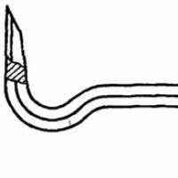 Gost scrap of ferrous metals (download) Scrap for construction gost 1405 83
 How many kilometers is the Moscow Moscow Ring Road in a circle?
 Where did the Moscow sparrows disappear: the conclusion of ornithologists Why did the sparrows disappear?
 How to make money on homemade toys?
 Creative business: making handmade toys