Technology for fine polishing of optical parts. Manufacturing and control of optical parts - A.A. Efremov Auxiliary technological operations
Ministry of Education of the Republic of Belarus
Educational institution
"BELARUSIAN STATE UNIVERSITY
INFORMATICS AND RADIO ELECTRONICS "
"TECHNOLOGICAL PROCESS OF PROCESSING
OPTICAL PARTS (general basics) "
MINSK, 2008
Basic technological operations
The technological process of manufacturing optical parts consists in processing their working and fastening surfaces. The blanks (lumpy glass, tiles, pressing, etc.) are given the required dimensions, and the surfaces - the structure according to their purpose.
When drawing up the most expedient technological process, the type of raw material, the number of parts in the batch, the available technical means (equipment, tools, etc.) and the required manufacturing accuracy must be taken into account. The processing of many optical parts can be divided into several main stages, each of which has a specific purpose.
Blank. Blanking operations are the removal of excess material, giving the workpiece an exact shape, maintaining the required dimensions, providing the required surface structure (matte) for subsequent fine grinding.
Operations for obtaining a semi-finished product can be very diverse. This is glass cutting, sawing, milling, drilling, rounding, roughing, medium grinding, chamfering, etc. Processing is carried out with abrasives in a free or bound state (wheels, cutters, diamond cermet tools). In many operations (spherical grinding, centering, milling, faceting), a tool made of synthetic diamonds on a cermet bond is widely used.
Auxiliary operations (sticking, gluing, blocking, etc.) are used to fix parts on devices and group them for joint further processing or to remove all kinds of contaminants (washing, wiping).
Fine grinding. This is the preparation of the surface of the optical part for polishing, that is, the removal of allowances on the workpiece and bringing the dimensions of the sides to the specified ones due to sequential processing with abrasives of various sizes (so-called transitions). Fine sanding results in a matt surface texture with a very fine structure.
Abrasive grains, when rolling between the glass and the sander, damage the glass with their cutting edges. Due to the shock-vibration action of the abrasive grains, a damaged surface layer (protrusions and concave fractures) is formed on the glass, and an inner fractured layer underneath. The depth of the fractured layer is several times (4 or more) greater than the depth of the outcrops of the surface layer (research by N.N.Kachalov, K.G. Kumanin and other scientists).
If there is an excess of water during grinding, the grains are washed off, the pressure on each remaining grain increases, they are crushed or jammed. In this case, scratches and gouges are inevitable. Excessive abrasive, preventing the grains from rolling freely, causes scratches, and reduces productivity. Grinding is most productive when the abrasive grains are distributed in one layer.
The spindle rotation speed affects the rolling frequency of the grains and their shock and vibration effect. An excessive increase in speed causes, under the influence of centrifugal force, the dropping of the not yet spent grains.
The amount of grinding is proportional to the amount of pressure. In practice, the limit is the pressure at which the grain is crushed (crushing force). Its value depends on the strength of the abrasive used.
It was found that water causes chemical processes on the glass surface, as a result of which wedging forces are created, which contribute to the separation of glass particles from the treated surface.
Polishing. This is the operation of removing the remaining irregularities on the surface of the optical part after fine grinding until the required class of roughness and cleanliness is obtained, as well as until the specified accuracy in the flatness or curvature of the machined surface is obtained. The process is based on the combined action of a number of factors: mechanical, chemical and physicochemical
Experiments have shown that the use of a variety of wetting liquids can speed up or slow down the polishing process. It has been proved that silicon compounds of glass under the influence of water form the thinnest (from 0.0015 to 0.007 microns) film, which stops the access of water to the deeper layers of glass and its chemical effect on them. Due to mechanical forces, this film breaks off, exposing a fresh layer of glass, which is again exposed to water. As a result, a new layer of film is formed, which immediately breaks off, etc. The film itself is capable of holding particles of the polishing material on its surface by adhesion forces.
Plates, mushrooms and cups are used as polishing tools, on which a layer of resin or fibrous materials is applied
For double-sided polishing of stained-glass, mirror, building glasses, decoration of high-quality glassware, the improvement of methods of chemical (acid) treatment of the glass surface by etching is of great importance. This method can be used instead of mechanical polishing of the glass surface, sometimes in combination with mechanical methods.
Centering. This is an operation of machining a part in diameter symmetrically to its optical axis, in which both the optical and geometric axes of the lens are aligned. The need to perform the operation is due to the following circumstances. In the process of manufacturing blanks, for example, when rounding columns (Fig. 1, a), roughing, grinding and polishing due to uneven removal of the glass layer, the lenses can have a wedge shape, which is characterized by uneven thickness of the parts along the edge (Fig. 1, b). For such a part, when a sphere is applied, the centers of the spherical surfaces are displaced, and, consequently, the optical axis relative to the geometric axis of the lens.
Fig. 1. Decentering education scheme:
a - misalignment of the axis of the column of workpieces; b - displacement of the center of the spherical surface

Rice. 2. Decentration in the lens:
a - the optical axis is parallel to the geometric axis; b - optical axis at an angle of the geometric axis

Rice. 3 Schematic representation

Fig. 4. Automatic lens setting by compression between sockets:
1 lens; 2-rounds
The optical axis of the lens before the centering operation can be parallel to its geometric axis (Fig. 2, a) or go at a certain angle to it (Fig. 2, b). In such a lens, its edges are located at different distances from the optical axis and have different thicknesses. Such a lens cannot be placed in the frame of the device, since the image will be poor (the optical axis of the lens does not coincide with the geometric axis of the frame). For a centered lens, the edges have the same thickness, and the optical and geometric axes are aligned within the tolerance for decentering (Fig. 3, b).
Installation of the lens on the holder before centering is carried out optically or mechanically.
Optical method - installation by "glare" on the eye or under the optical tube. The lens is fixed with a centering resin on a rotating cartridge in a position at which the image of the lamp thread or the image of the "flare" in the optical tube is immobile.
The mechanical method (self-centering) is that the lens is installed automatically by compression between two cartridges located strictly on the same axis (Fig. 4).
With both methods, the correct installation is guaranteed by good preparation and trimming of the mounting edge of the chucks and the absence of beating of the centering part during rotation.
Gluing. The task of gluing is to obtain a rigidly fastened and centered system.
In some cases (especially for flat parts), gluing is replaced by optical contact (molecular adhesion of two polished surfaces).
Auxiliary technological operations
The most important auxiliary blocking operation is the connection of parts or workpieces with a device (sticker, mechanical method, optical contact method, vacuum fastening, seating in separators, etc.) for their further joint processing. The combination of a fixture and parts or workpieces fixed to it is called a block. The quality of the product and the economy of the technological process largely depend on the correct choice of the blocking method, depending on the size and shape of the parts, the specified accuracy.
The blocking should provide:
1) securing the largest possible number of workpieces;
2) ease of processing in this operation (for example: grinding, polishing);
3) convenience to make the necessary measurements in the process;
4) reliability of fastening at the most intensive operating conditions;
5) absence of mechanical damage and deformation of workpieces or parts;
6) the correct and symmetrical arrangement of the treated surfaces relative to the fixture and the processing tool;
7) simplicity and speed of locking and unlocking.
There are several blocking methods used in optical production. However, the most common method is still elastic fastening.
Elastic fastening. It is used in small-scale and mass production for medium precision parts. This operation includes the following transitions:
1. Sticking resin pads on one of the processed sides of the part by hand or on a special semiautomatic device.
2. Cleaning the second treated surface of the lens
3. Lapping the lenses to the thoroughly cleaned surface of the lapping device (mushroom, cup, faceplate).
4. Gluing parts to an adhesive device.
5. Cooling the unit.
The thickness of the resin layer after cooling should be 0.1-0.2d (d is the lens diameter), but not less than 1 mm (for small diameter lenses). So, for example, for a lens with a diameter of 30 mm, the height of the resin pad is 3-6 mm. The diameter of the resin pad is equal to the diameter of the part and is made with a slight taper for easy blocking (Figure 5). Unlocking is done in the refrigerator, and sometimes just with a wooden mallet.
Fill is used for lenses of small diameter and small radius of curvature. The lenses are dripped from above with molten resin onto the lenses that are ground in and, respectively, located on the surface of the grinding device. The resin fills the cup, heats up the lenses and adheres to them. Until the resin hardens, a heated adhesive device, such as a mushroom, is inserted into it. After sufficient immersion in the resin and leveling so that the axes of the fixtures are aligned, the block is cooled. After cleaning, the surface of the block is rinsed with solvent and water. Unlocking is done by warming up the block.
Rigid mount. It is used in mass and large-scale production of parts with surface accuracy tolerances of 0.5 rings or more, for a thickness of 0.05 mm and more.
To process the first side, the lenses (pressing) are rigidly glued directly onto the device in special sockets or platforms (Fig. 6, a).

Rice. 5. Kind of resin pillows
The device is heated to a temperature of about 100 ° C. At the same time, the parts are slightly heated. A thin layer of resin or tarred cloth gasket is applied to the fixing surface of the fixture (when processing the second side). After applying the lenses with a stick, the resin from under the part survives as much as possible. After processing the first side (roughing or milling, medium and fine grinding, polishing), the entire surface of the part is varnished and processed in the same sequence on the second side.
Semi-rigid mount. Used for thin lenses with a large radius of curvature of the treated surface. The lens is glued with a tarred cloth gasket on a metal washer, in turn, glued to the device (Fig. 6, b). In spectacle production, heated blanks are glued directly onto the resin layer. To ensure the accuracy of such an attachment, a special tool molds reverse-shaped seats on the resin layer. They determine the place of the lenses when blocking (Fig. 6, c).
Mechanical fastening. Most often it is used for blanking operations, for example, for attaching prisms.
The parts are placed close to each other in metal fixtures with corresponding cutouts. The end pieces are held in place by screw or spring clips. An elastic gasket (rubber, cardboard) is placed under the extreme parts.

Rice. 6. Label scheme (hard and semi-hard methods):
a - tough method; b - semi-rigid method; c - sticker on resin protrusions
(1 - lens; 2 - tarred cloth gasket; 3 - spherical plate;
4 - resin; 5 - adhesive device);
Plasterboard. The method is used most often for attaching prisms with angle tolerances from 3 "and higher and large pieces of glass. Plastering consists of pouring an aqueous solution of gypsum with cement into a device in the form of a pot, body, etc. (Fig. 7) directly on the part The bottom of the pot is attached to the ring with screws or in another way. Often limited to a rubber rim wrapping the lapping plate. After the plaster has hardened and the bottom installed directly into the plaster is fixed in it, the rim is removed.

Rice. 7. Plastering scheme:
1 - prism; 2 - lapping faceplate; 3 - plate; 4 - bottom; 5 - the ring of the body with prisms after the gypsum has hardened is cleaned with a wire brush to a depth of 2-3 mm and washed.
To ensure the cleaning of the block, the space between the prisms is covered with finely sifted dry sawdust before pouring, and the metal rim is placed on 3-4 plates with a thickness of 2-3 mm. To protect against moisture and plaster shedding, the cleaned space is covered with molten paraffin.
Unlocking is done by splitting the plaster with a wooden hammer or using a special de-plastering press. The use of a press reduces the laboriousness of the unblocking process and ensures a higher quality, since almost all prisms are completely free of plaster.
Optical contact method. When machining parts with precise surfaces (up to 0.05 rings), angular dimensions 1-2 ", parallelism 1-10" (precision plates, mirrors, wedges, prisms), optical contact fastening is used. At the same time, the surfaces of parts polished "with color" 0.5-2 rings are thoroughly cleaned and degreased (alcohol, ether, squirrel brush, cambric wipes) and gently lowered and pressed against the also carefully prepared polished surface of the contact device. Pressing is carried out until the interference pattern disappears. The gap between the parts is covered with varnish, or a solution of shellac in rectified.
Contact devices can be of different shapes and sizes (Fig. 8) depending on the shape and size


Rice. 8. Contact devices for plates and prisms: a - contact plate with plane-parallel plates (1 - plates; 2 - contact plate); b - a device for prisms and wedges (1 - prisms; 2 - contact device) of the processed parts.
Their surface must be polished with an accuracy of 0.1-0.5 rings. If parallelism is required, it can be maintained up to 1-2 ”. The accuracy of the angles is also strictly maintained, since the quality of the product depends on the accuracy of the angular dimensions, parallelism and the quality of the surface of the contact devices.
When removing from contact, heating or cooling is applied. Thin parts (0.1-0.5 mm) can be carefully removed with a razor blade or a drop of ether poured onto the surface of the part.
Fastening in separators. Separators or dividing devices are used in the workpiece and in final operations with precise surface finishing and angular dimensions. The separator is a holder with cutouts into which the workpieces are placed. Processing of such parts, for example, in a workpiece, can be carried out simultaneously from both sides (Fig. 9, a). For precise finishing, thick glass plates with cutouts of different diameters are used, into which various parts are laid (Fig. 9, b). The cutouts prevent the part from falling outside the pad.


Rice. 9. Separator: a - scheme of double-sided grinding (1 - separator; 2 - plates; 3 - grinders); b-glass separator for mechanized finishing of flat parts
The separator itself, in the process of operation, constantly corrects the surface of the polishing pad, thereby maintaining it in good condition, that is, it is also a forming disc.
If on a part (plate, wedge) it is necessary to increase or decrease the angle of the wedge, then a load is glued to its edge with soft wax, due to which a stronger response of the desired area occurs.
The ratio of the area of the holes and the whole part of the separator is determined by calculation.
Manufacturing a set of grinders
Grinding a convex surface when changing from coarser to finer abrasives always starts at the edge. This ensures that the desired lens thickness is maintained in the center and that the entire surface is uniformly ground from the edges to the center. The radii of curvature of the grinding tool are changed by undercutting when moving from coarser to finer abrasives.

Rice. 10. Schematic images of changes in the radius of curvature of the surface of the tool cup (a) and mushroom (b):
R 1 - radius of curvature of the roughing tool; R 2 - radius of curvature of the tool for medium grinding; R 3 - radius of curvature of the tool for fine grinding
The radii of curvature of the cups gradually decrease (Fig. 10, a), while those of mushrooms, on the contrary, increase (Fig. 10, b).
When grinding the tool, the surface is given the desired radius of curvature or precise flatness. At the same time, the surface is ground until the traces of the cutter or scraper are removed.
The sequence of the operation is as follows.
1. The surface of the tool for the last stage of grinding is adjusted by trimming according to a template of a given radius and after that a block of rejected parts is blocked on it.
2. The block is ground and polished on the same tool. An interference pattern ("color") is viewed.
3. If the "color" does not meet the requirements for this set of grinders, then re-trim the grinder, re-grind, polish and review the "color".

Rice. 11. Lapping scheme:
a - surfaces of small curvature; b - surfaces of large curvature (D bl - block diameter)
4. Upon reaching the required "color" the tool is ground until the traces of the cutter or scraper are removed and the block is finally checked again against the test glass.
5. When the last grinder is prepared, for example, for grinding with M10 micropowder, adjustment (already by lapping) of the grinder preceding the last one is performed, for example, for grinding with M20 micropowder. To do this, a test block is ground on it and its lapping is adjusted to the tool for the last grinding. Blocks with small curvature (with large radii of curvature) should be rubbed in at least ¼ of their diameter, and blocks with large curvature by 1 / 6-1 / 7 of the diameter (Fig. 11). In production, there are still names: "weak radii" (large radii of curvature), "strong radii", or "steep spheres" (small radii of curvature). These names should not be used.
6. Under the straightened grinder fit the previous one, etc. until the whole set is adjusted.


Methyl bromide (CH3Br) and methylene bromide (CH2Br2) were widely used in the production of halogen lamps. 2 The technological process of manufacturing a quartz halogen lamp 2.1 Physical properties of quartz glass and methods of its processing A significant reduction in the overall dimensions of halogen lamps and the need to create conditions for the operation of the halogen cycle required high ...
Ministry of Education of the Republic of Belarus
Educational institution
"BELARUSIAN STATE UNIVERSITY
INFORMATICS AND RADIO ELECTRONICS "
ESSAY
On the topic:
"TECHNOLOGICAL PROCESS OF PROCESSING
OPTICAL PARTS (general basics) "
MINSK, 2008
Basic technological operations
The technological process of manufacturing optical parts consists in processing their working and fastening surfaces. The blanks (lumpy glass, tiles, pressing, etc.) are given the required dimensions, and the surfaces - the structure according to their purpose.
When drawing up the most expedient technological process, the type of raw material, the number of parts in the batch, the available technical means (equipment, tools, etc.) and the required manufacturing accuracy must be taken into account. The processing of many optical parts can be divided into several main stages, each of which has a specific purpose.
Blank. Blanking operations are the removal of excess material, giving the workpiece an exact shape, maintaining the required dimensions, providing the desired surface structure (matte) for subsequent fine grinding.
Operations for obtaining a semi-finished product can be very diverse. This is glass cutting, sawing, milling, drilling, rounding, roughing, medium grinding, chamfering, etc. Processing is carried out with abrasives in a free or bound state (wheels, cutters, diamond cermet tools). In many operations (spherical grinding, centering, milling, faceting), a tool made of synthetic diamonds on a cermet bond is widely used.
Auxiliary operations (sticking, gluing, blocking, etc.) are used to fix parts on devices and group them for joint further processing or to remove all kinds of contaminants (washing, wiping).
Fine grinding... This is the preparation of the surface of the optical part for polishing, that is, the removal of allowances on the workpiece and bringing the dimensions of the sides to the specified ones due to sequential processing with abrasives of various sizes (so-called transitions). Fine sanding results in a matt surface texture with a very fine structure.
Abrasive grains, when rolling between the glass and the sander, damage the glass with their cutting edges. Due to the shock-vibration action of the abrasive grains, a damaged surface layer (protrusions and concave fractures) is formed on the glass, and an inner fractured layer underneath. The depth of the fractured layer is several times (4 or more) greater than the depth of the outcrops of the surface layer (research by N.N.Kachalov, K.G. Kumanin and other scientists).
If there is an excess of water during grinding, the grains are washed off, the pressure on each remaining grain increases, they are crushed or jammed. In this case, scratches and gouges are inevitable. Excessive abrasive, preventing the grains from rolling freely, causes scratches, and reduces productivity. Grinding is most productive when the abrasive grains are distributed in one layer.
The spindle rotation speed affects the rolling frequency of the grains and their shock and vibration effect. An excessive increase in speed causes, under the influence of centrifugal force, the dropping of the not yet spent grains.
The amount of grinding is proportional to the amount of pressure. In practice, the limit is the pressure at which the grain is crushed (crushing force). Its value depends on the strength of the abrasive used.
It was found that water causes chemical processes on the glass surface, as a result of which wedging forces are created, which contribute to the separation of glass particles from the treated surface.
Polishing... This is the operation of removing the remaining irregularities on the surface of the optical part after fine grinding until the required class of roughness and cleanliness is obtained, as well as until the specified accuracy in the flatness or curvature of the machined surface is obtained. The process is based on the combined action of a number of factors: mechanical, chemical and physicochemical
Experiments have shown that the use of a variety of wetting liquids can speed up or slow down the polishing process. It has been proved that silicon compounds of glass under the influence of water form the thinnest (from 0.0015 to 0.007 microns) film, which stops the access of water to the deeper layers of glass and its chemical effect on them. Due to mechanical forces, this film breaks off, exposing a fresh layer of glass, which is again exposed to water. As a result, a new layer of film is formed, which immediately breaks off, etc. The film itself is capable of holding particles of the polishing material on its surface by adhesion forces.
Plates, mushrooms and cups are used as polishing tools, on which a layer of resin or fibrous materials is applied
For double-sided polishing of stained-glass, mirror, building glasses, decoration of high-quality glassware, the improvement of methods of chemical (acid) treatment of the glass surface by etching is of great importance. This method can be used instead of mechanical polishing of the glass surface, sometimes in combination with mechanical methods.
Centering. This is an operation of machining a part in diameter symmetrically to its optical axis, in which both the optical and geometric axes of the lens are aligned. The need to perform the operation is due to the following circumstances. In the process of manufacturing blanks, for example, when rounding columns (Fig. 1, a), roughing, grinding and polishing due to uneven removal of the glass layer, the lenses can have a wedge shape, which is characterized by uneven thickness of the parts along the edge (Fig. 1, b). In such a part, when a sphere is applied, the centers of the spherical surfaces are displaced, and, consequently, the optical axis relative to the geometric axis of the lens.
Fig. 1. Decentering education scheme:
a - misalignment of the axis of the column of workpieces; b - displacement of the center of the spherical surface
Rice. 2. Decentration in the lens:
a - the optical axis is parallel to the geometric axis; b - optical axis at an angle of the geometric axis
Rice. 3 Schematic representation
Fig. 4. Automatic lens setting by compression between sockets:
1 lens; 2-rounds
The optical axis of the lens before the centering operation can be parallel to its geometric axis (Fig. 2, a) or go at a certain angle to it (Fig. 2, b). In such a lens, its edges are located at different distances from the optical axis and have different thicknesses. Such a lens cannot be placed in the frame of the device, since the image will be poor (the optical axis of the lens does not coincide with the geometric axis of the frame). For a centered lens, the edges have the same thickness, and the optical and geometric axes are aligned within the tolerance for decentering (Fig. 3, b).
Installation of the lens on the holder before centering is carried out optically or mechanically.
Optical method - installation by "glare" on the eye or under the optical tube. The lens is fixed with a centering resin on a rotating cartridge in a position at which the image of the lamp thread or the image of the "flare" in the optical tube is immobile.
The mechanical method (self-centering) is that the lens is installed automatically by compression between two cartridges located strictly on the same axis (Fig. 4).
With both methods, the correct installation is guaranteed by good preparation and trimming of the mounting edge of the chucks and the absence of beating of the centering part during rotation.
Gluing. The task of gluing is to obtain a rigidly fastened and centered system.
In some cases (especially for flat parts), gluing is replaced by optical contact (molecular adhesion of two polished surfaces).
Auxiliary technological operations
The most important auxiliary blocking operation is the connection of parts or workpieces with a device (sticker, mechanical method, optical contact method, vacuum fastening, seating in separators, etc.) for their further joint processing. The combination of a fixture and parts or workpieces fixed to it is called a block. The quality of the product and the economy of the technological process largely depend on the correct choice of the blocking method, depending on the size and shape of the parts, the specified accuracy.
The blocking should provide:
1) securing the largest possible number of workpieces;
2) ease of processing in this operation (for example: grinding, polishing);
3) convenience to make the necessary measurements in the process;
4) reliability of fastening at the most intensive operating conditions;
5) absence of mechanical damage and deformation of workpieces or parts;
6) the correct and symmetrical arrangement of the treated surfaces relative to the fixture and the processing tool;
7) simplicity and speed of locking and unlocking.
There are several blocking methods used in optical production. However, the most common method is still elastic fastening.
Elastic mount... It is used in small-scale and mass production for medium precision parts. This operation includes the following transitions:
1. Sticking resin pads on one of the processed sides of the part by hand or on a special semiautomatic device.
The most effective technological operation that allows you to bring the surface of metal parts to an ideal state is lapping. Parts that have been exposed to this procedure can form leak-proof or tight-fitting joints. The need for the formation of such compounds and, accordingly, in the technological operation performed with the help of special tools and materials, exists in many areas of activity.
The essence of technology
Lapping, due to which it is possible to obtain surfaces with the required degree of roughness and with given deviations, involves the removal of a thin layer of metal from the workpiece, for which, in contrast to the finishing operation of scraping, not only tools are used, but also fine abrasive powders or pastes. The abrasive material with which such processing is performed can be applied both to the surface of the part and to a special device called a lap.

Lapping, carried out at a slow speed and with the help of constantly changing direction of movements, allows not only to reduce the surface roughness to the required value, but also to significantly improve its physical and mechanical characteristics.
Lapping, which is often referred to as lapping, can be done in a variety of ways. So, parts of a complex configuration, manufactured in single copies, are processed completely by hand, and for grinding in products manufactured in small batches, a semi-mechanical method is used. In this case, the supply of the part to the processing zone is carried out manually, and the grinding itself is performed using mechanical devices. In the production of parts in large batches and in large quantities, one cannot do without such a device as a lapping machine, with the help of which finishing operations are performed.

Special devices and materials
As mentioned above, in order to carry out, you need a special tool called a lap. According to the shape of the working surface, such devices are divided into the following types:
- lapping tool of flat type;
- with an inner surface of a cylindrical type;
- with an outer cylindrical surface;
- conical type tool.

When choosing a material for the manufacture of a lapping tool, pay attention to the fact that its hardness is significantly lower than the hardness of the material of manufacture of the workpiece. This requirement is due to the fact that the abrasive powder or paste, with the use of which the lapping is performed, could be retained by the material of the tool. So, the most common raw materials for the manufacture of such a device are:
- gray cast iron;
- copper;
- lead;
- soft steel;
- various types of wood;
- other metals and non-metallic materials.

To perform preliminary and final lapping operations, tools are used of both various designs and made from all kinds of materials. For example, to perform preliminary operations when using a coarser abrasive material, a tool made of softer materials is used. On its working surface, grooves are pre-cut to hold the abrasive, the depth of which is 1–2 mm. The final processing of products, carried out using a finely dispersed abrasive, is carried out with a device, the working surface of which is completely smooth. The material for the manufacture of tools for performing finishing operations is mainly cast iron. Using lapping tools, which are made of lead and wood, the surfaces of the workpieces are given a shine.

Abrasive powder is the main material for effective and efficient lapping. Such powders, depending on the material of manufacture, are divided into hard (the hardness of the material is higher than that of) and soft (their hardness is lower than that of hardened steel). For the manufacture of powders of the first type, corundum, corundum and emery are used, and the second - chromium oxide, Viennese lime, crocus, etc. According to the degree of granularity, abrasive powders are also divided into several categories. You can even distinguish powders and pastes of different categories from each other by their color. So, pastes based on coarse-grained powder are light green, medium-grained - dark green, pastes with fine powder - greenish-black.
The most famous variety of the last type of pastes, with the help of which finishing lapping operations are performed, is GOI paste.
Many home locksmiths make their own powders and pastes for lapping. It is quite easy to do this: for this it is necessary to thoroughly grind the pieces of an emery wheel in a massive mortar, and then sift the resulting powder through a sieve with very fine cells.

The efficiency and quality of lapping, in addition to the equipment used and the abrasive material, is seriously affected by the lubricant used. Various substances can be used as such material:
- turpentine;
- mineral oil;
- kerosene;
- animal fats;
- alcohol or aviation kerosene.
The last two substances are used in cases where increased requirements are imposed on the quality of lapping.

Tools and fixtures
The most common finishing tool is the lapping plate, which, as mentioned above, can be made from a variety of materials. The choice of the type and material of manufacture of such a plate, which is a fairly universal device, is influenced by both the features of the processed parts and the requirements for the quality of the lapped surface. Among all types of plates, the most widespread are products made from grades of cast iron, the hardness of which (according to HB) is in the range of 190-230 units.

The design and dimensions of a plate or another type of lapping tool are influenced by both the design features of the processed products and the type of processing: rough or finishing. It is the plates as a device for lapping that are used to process flat surfaces. In this case, as already mentioned above, special grooves are applied to the surface of the plates used for roughing operations, which can also have a spiral configuration. Such grooves not only keep the abrasive material in the lapping area, but also remove waste from it.
Naturally, it is not possible to grind cylindrical surfaces, holes and parts with a complex configuration using a plate. Therefore, for such purposes, a device is made, the shape of which is optimal for processing a part of a certain configuration. So, it can be lapping tools of round, cylindrical, annular, conical, disk configuration, etc. In particular, it is performed by a device that is made in the form of bushings fixed on special mandrels.
The tool with which the lapping operations are performed is also divided into fixed and adjustable. The device of the second type is more versatile, its design, consisting of a split working part, a cone and a sliding device, provides for the possibility of changing its diameter.
For processing cylindrical parts, it is not at all necessary to use a specialized lapping machine; for this, a universal turning or drilling equipment is quite suitable. In such cases, the workpiece to be processed can be fixed in the centers or in the chuck of the equipment, depending on which part of its surface needs to be ground in.

Machines that were originally designed for lapping are classified into general-purpose equipment and specialized models. On general-purpose machines, which can be equipped with one or two lapping tools, workpieces with flat and cylindrical surfaces are predominantly processed. Smaller parts, when machined on such machines, in a free state, are placed in a special separator, where they undergo lapping, located between two rotating lapping discs. Large parts are fixed on the machine using a special device and processed with one abrasive disc.

More complex in design and less versatile are specialized machines, the device of which is specially designed for grinding parts of a certain configuration: valve seats, camshaft cams, crankshaft journals, gear wheels, etc.
Such machines, which have high productivity and provide high quality lapping, are used in large-scale and mass production, therefore, innovative technical solutions are often implemented in their designs: self-centering centrifugal chucks, devices for automatically adjusting the clamping force, etc.
Unified tariff and qualification reference book of jobs and professions of workers (ETKS). Issue No. 71
Approved by the Decree of the State Committee for Labor of the USSR, All-Union Central Council of Trade Unions of 24.07.1985 N 239 / 16-26
Optical polisher
§ 67. Polisher of optical parts of the 2nd category
Description of works... Fine grinding and polishing of simple optical glass parts on semi-automatic and universal grinding and polishing equipment. Grinding of grinding tools on grinding and polishing machines of various types with a surface quality tolerance for common errors of more than 0.3 of the interference ring.
Must know: device and rules for the use of grinding and polishing machines; setting up machines and the process of grinding the tool for a ruler, template; device, purpose and use of control and measuring tools and instruments; brands and grades of optical glasses; marking and characteristics of abrasive materials; used auxiliary materials; general information about the system of tolerances and landings, qualities, roughness parameters and processing cleanliness classes.
Work examples
1. Flat optical parts with a larger side or diameter over 10 to 50 mm with a thickness to diameter or larger side ratio of more than 0.1 - fine grinding and polishing according to VI - VII cleanliness classes with tolerances: for surface quality by total errors of more than 1 , 5 interference rings per 1 cm of surface, for local errors over 0.7 rings, for a thickness of over 0.6 mm, for a wedge over 7 to 10 minutes.
2. Flat optical parts with a larger side or diameter over 50 to 100 mm and up to 10 mm, complex parts with a larger side or diameter over 10 to 50 mm with a ratio of thickness to diameter or larger side over 0.15 - fine grinding and polishing according to the VIII class of cleanliness with tolerances: for the surface quality for general errors of more than 2.0 of the interference ring per 1 cm of the surface, for local errors of more than 1.0 of the ring, for a thickness of over 0.5 mm, for a wedge for more than 7 minutes.
3. Lens plano-convex, biconvex and meniscus positive with a diameter of over 10 to 50 mm with a ratio of thickness to diameter over 0.09 - fine grinding and polishing according to VI - VII cleanliness classes with tolerances: for surface quality by general errors over 2.0 an interference ring per 1 cm of the surface, for local errors over 0.7 of a ring, for a thickness of over 0.4 mm.
4. Lenses are plano-convex, biconvex and menisci positive with a diameter of over 50 to 100 mm and up to 10 mm, complex lenses with a diameter of over 10 to 50 mm with a ratio of thickness to diameter over 0.2 - fine grinding and polishing according to the VII class of purity with tolerances: on the surface quality for general errors of more than 2.0 of the interference ring per 1 cm of the surface, for local errors of more than 1.0 of the ring.
§ 68. Polisher of optical parts of the 3rd category
Description of works... Fine grinding and polishing of parts of medium complexity made of optical glass, crystals and ceramics on semi-automatic and universal grinding and polishing equipment.
Must know: rules for setting up grinding and polishing machines; physicochemical properties of optical glasses, crystals and other optical materials; manufacturing methods and techniques for adjusting the tool; rules for the use of optical devices for checking the linear and angular dimensions of optical parts; system of tolerances and landings, qualities, roughness parameters and processing purity classes.
Work examples
1. Flat optical parts with a larger side or diameter over 10 to 50 mm with a ratio of thickness to diameter or larger side over 0.05 to 0.09 - fine grinding and polishing according to IV - V cleanliness classes with tolerances: for surface quality according to general errors of more than 0.8 to 1.0 of the interference ring per 1 cm of the surface, for local errors of more than 0.5 to 0.7 of the ring, for a thickness of over 0.3 to 0.6 mm, for a wedge over 5 to 6 minutes.
2. Flat optical parts with a larger side or diameter over 50 to 100 mm and up to 10 mm, complex parts with a larger side or diameter over 10 to 50 mm with a ratio of thickness to diameter or larger side over 0.05 to 0.15 - fine grinding and polishing according to V - VII cleanliness classes with tolerances: for surface quality by general errors over 1.0 to 1.5 interference rings per 1 cm of surface, by local errors over 0.7 to 1.0 rings, by thickness over 0.4 to 0.5 mm, for a wedge over 5 to 7 minutes.
3. Flat optical parts with a larger side or diameter over 100 to 500 mm, complex parts with a larger side or diameter over 50 to 100 mm and up to 10 mm with a ratio of thickness to diameter or larger side over 0.15 - fine grinding and polishing for VIII - IX cleanliness classes with tolerances: for surface quality for general errors over 1.0 of an interference ring per 1 cm of surface, for local errors over 0.7 rings, for a thickness of over 0.3 mm, for a wedge over 10 minutes.
4. Flat optical parts with a larger side or a diameter of more than 500 mm, complex with a larger side or a diameter of more than 100 mm with a side ratio of more than 6 to 10 or with a thickness to diameter or larger side ratio of more than 0.2 - fine grinding and polishing according to the VIII class of cleanliness with tolerances: for surface quality for general errors of more than 2.0 interference rings per 1 cm of surface, for local errors of more than 1.5 rings, for a thickness of more than 1.5 mm, for a wedge for more than 10 minutes.
5. Polished optical parts with a diameter over 10 to 200 mm - chamfering with a diamond tool or abrasive.
6. Wedges and prisms with 1 and 2 reflective surfaces of types AR, BR, BS, BU with a larger side size of more than 10 to 50 mm - fine grinding and polishing according to IV - VII cleanliness classes with tolerances: for surface quality by total errors of more than 1 , 0 interference ring per 1 cm of surface, for local errors over 0.5 of the ring, for angles and pyramidality over 5 minutes.
7. Wedges and prisms with a larger side size over 50 to 100 mm and up to 10 mm, complex ones with a larger side size over 10 to 50 mm - fine grinding and polishing according to the VII class of cleanliness with tolerances: for surface quality by total errors of more than 1, 5 interference rings per 1 cm of surface, for local errors over 0.7 rings, for angles and pyramidality over 10 minutes.
8. Lenses are plano-convex, biconvex, menisci positive with a diameter of over 10 to 50 mm with a ratio of lens thickness to diameter over 0.05 to 0.09 - fine grinding and polishing according to IV-V cleanliness classes with tolerances: for surface quality according to general errors of more than 1.5 to 2.0 of the interference ring per 1 cm of the surface, for local errors of more than 0.5 to 0.7 of the ring, for a thickness of over 0.15 to 0.4 mm.
9. Lenses are plano-convex, biconvex, menisci positive with a diameter of over 50 to 100 mm and up to 10 mm, complex lenses with a diameter of over 10 to 50 mm with a ratio of thickness to diameter over 0.1 to 0.2 - fine grinding and polishing according to IV - VI cleanliness classes with tolerances: for surface quality by general errors of more than 1.5 to 2.0 of an interference ring per 1 cm of surface, by local errors of more than 0.7 to 1.0 rings, for a thickness of more than 0.4 to 0.5 mm.
10. Lenses are plano-convex, biconvex, positive menisci with a diameter of over 100 to 250 mm, complex lenses with a diameter of over 50 to 100 mm and up to 10 mm with a thickness-to-diameter ratio of over 0.2 - fine grinding and polishing according to VIII-IX purity classes with tolerances: for surface quality for general errors over 1.0 of an interference ring per 1 cm of surface, for local errors of over 1.0 rings, for a thickness of over 0.2 mm.
§ 69. Polisher of optical parts of the 4th grade
Description of works... Fine grinding and polishing of complex parts made of optical glass, crystals and ceramics on semi-automatic and universal grinding and polishing equipment.
Must know: rules for setting up instruments for checking linear, angular dimensions and optical characteristics; technological features of processing various brands of optical glass; methods of finishing purity and color; device of various devices and methods of their manufacture.
Work examples
1. Flat optical parts with a larger side or diameter over 10 to 50 mm with a ratio of thickness to diameter over 0.03 to 0.05 - fine grinding and polishing according to the III class of cleanliness with tolerances: for surface quality by general errors over 0, 6 to 0.8 interference rings per 1 cm of surface, for local errors over 0.3 to 0.5 rings, for a thickness of over 0.1 to 0.3 mm, per wedge over 3 to 4 minutes.
2. Flat optical parts with a larger side or diameter over 50 to 100 mm and up to 10 mm, complex parts with a larger side or diameter over 10 to 50 mm with a ratio of thickness to diameter or larger side over 0.06 to 0.1 - fine grinding and polishing according to IV-V cleanliness classes with tolerances: for surface quality by general errors of more than 0.6 to 1.0 of an interference ring per 1 cm of surface, for local errors of more than 0.5 to 0.7 rings, for a thickness of over 0.1 to 0.4 mm, for a wedge over 4 to 5 minutes.
3. Flat optical parts with a larger side or diameter over 100 to 500 mm, complex parts with a larger side or diameter over 50 to 100 mm and up to 10 mm with a ratio of thickness to diameter or larger side over 0.05 to 0.15 - fine grinding and polishing according to V - VII cleanliness classes with tolerances: for surface quality by general errors of more than 0.3 to 1.0 of an interference ring per 1 cm of surface, for local errors of more than 0.5 to 0.7 rings, for a thickness of over 0.3 mm, for a wedge over 5 minutes.
4. Flat optical parts with a larger side or diameter over 500 mm, complex with a larger side or diameter over 100 mm with a side ratio of more than 10 to 15 or with a thickness to diameter or larger side ratio of more than 0.08 to 0.2 - fine grinding and polishing according to IV - VII cleanliness classes with tolerances: for surface quality by general errors of more than 1.0 to 2.0 of an interference ring per 1 cm of surface, by local errors of more than 1.0 to 1.5 rings, by a thickness of over 1.0 to 1.5 mm, for a wedge over 7 to 10 minutes.
5. Polished optical parts with a diameter of up to 10 and over 200 mm - chamfering with a diamond tool or free abrasive.
6. Wedges and prisms with 1 - 2 reflective surfaces of the types AKR, BP, BM with a larger side size over 10 to 50 mm - fine grinding and polishing according to the III class of cleanliness with tolerances: for surface quality by general errors of more than 0.5 to 1 , 0 interference ring per 1 cm of surface, for local errors over 0.3 to 0.5 rings, for angles and pyramidality over 1 to 5 minutes.
7. Wedges and prisms with 1 - 2 reflective surfaces of the types AkR, BP, BM with a larger side size over 50 to 100 mm and up to 10 mm, complex ones with a larger side size over 10 to 50 mm - fine grinding and polishing according to the VI class of cleanliness with tolerances: for the surface quality for general errors of more than 0.6 to 1.5 of the interference ring per 1 cm of the surface, for local errors of more than 0.5 to 0.7 of the ring, for angles and pyramidality for more than 4 to 10 minutes.
8. Wedges and prisms with 1 - 2 reflective surfaces of the types AKR, BP, BM with a larger side size over 100 mm, complex ones with a larger side size over 50 and up to 10 mm - fine grinding and polishing according to the VII class of purity with tolerances: for quality surfaces for general errors of more than 1.0 of the interference ring per 1 cm of the surface, for local errors of more than 0.7 of the ring, for angles and pyramidality for more than 8 minutes.
9. Lenses are plano-convex, biconvex, menisci positive and negative with a diameter of more than 10 to 50 mm with a ratio of thickness to diameter of more than 0.03 to 0.05 mm - fine grinding according to the III class of cleanliness with tolerances: for surface quality for general errors over 0.8 to 1.5 interference rings per 1 cm of surface, for local errors over 0.3 to 0.5 rings, for a thickness of 0.05 to 0.15 mm.
10. Lenses are plano-convex, biconvex, menisci positive and negative with a diameter of over 50 to 100 mm and up to 10 mm, complex lenses with a diameter of over 10 to 50 mm with a thickness-to-diameter ratio of over 0.02 to 0.05 - fine grinding and polishing according to IV - V cleanliness classes with tolerances: for surface quality for general errors of more than 1.0 to 1.5 of an interference ring per 1 cm of surface, for local errors of more than 0.5 to 0.7 rings, for a thickness of more than 0.1 to 0 , 4 mm.
11. Lenses are plano-convex, biconvex, menisci positive and negative with a diameter of over 100 to 250 mm, complex lenses with a diameter of over 50 to 100 mm and up to 10 mm with a ratio of thickness to diameter over 0.2 - fine grinding and polishing according to VIII-IX classes cleanliness with tolerances: for surface quality by general errors of more than 0.5 to 1.0 of an interference ring per 1 cm of surface, by local errors of more than 0.5 to 0.8 of a ring, by a thickness of over 0.3 mm.
12. Lenses are plano-convex, biconvex, menisci positive and negative with a diameter of over 250 mm, complex lenses with a diameter of over 100 mm with a thickness-to-diameter ratio of over 0.2 - fine grinding and polishing according to VII - IX cleanliness classes with tolerances: for surface quality according to general errors of more than 0.5 to 1.0 of the interference ring per 1 cm of the surface, for local errors of more than 0.3 of the ring, for a thickness of more than 0.05 mm.
Section 70. Polisher of optical parts of the 5th category
Description of works... Fine grinding and polishing of especially complex parts made of optical glass of all brands, crystals and ceramics on semi-automatic and universal grinding and polishing equipment.
Must know: technological features of processing soft and hard glasses, optical crystals and ceramics; sequence of using grinding and polishing materials.
Work examples
1. Flat optical parts with a larger side or diameter over 10 to 50 mm with a ratio of thickness to diameter or larger side up to 0.03 - fine grinding and polishing according to I - II cleanliness classes with tolerances: for surface quality according to general errors up to 0 , 6 interference rings per 1 cm of surface, for local errors up to 0.3 rings, for a thickness of up to 0.1 mm, for a wedge up to 3 minutes.
2. Flat optical parts with a larger side or diameter over 50 to 100 mm and up to 10 mm, complex parts with a larger side or diameter over 10 to 50 mm with a ratio of thickness to diameter or larger side up to 0.02 - fine grinding and polishing for II - IV cleanliness classes with tolerances: for surface quality by general errors of up to 0.6 of an interference ring per 1 cm of surface, for local errors of up to 0.5 rings, for a thickness of up to 0.1 mm, for a wedge up to 4 minutes.
3. Flat optical parts with a larger side or diameter over 100 to 500 mm, complex parts with a larger side or diameter over 50 to 100 mm and up to 10 mm with a ratio of thickness to diameter or larger side over 0.03 to 0.05 - fine grinding and polishing according to II - IV cleanliness classes with tolerances: for surface quality according to general errors of up to 0.3 interference ring per 1 cm of surface, for local errors up to 0.5 rings, for a thickness of up to 0.3 mm, for a wedge up to 5 minutes.
4. Flat optical parts with a larger side or diameter over 500 mm, complex with a larger side or diameter over 100 mm with a side ratio of up to 15 or with a thickness to diameter or larger side ratio of more than 0.05 to 0.08 - fine grinding and polishing according to II - III cleanliness classes with tolerances: for surface quality according to general errors up to 1.0 interference ring per 1 cm of surface, according to local errors up to 0.7 rings, for a thickness of up to 1.0 mm, for a wedge up to 5 minutes ...
5. Wedges and prisms with 1, 2, 3 reflective surfaces of the types VL, VK, VP with a larger side size over 10 to 50 mm - fine grinding and polishing according to I - II cleanliness classes with tolerances: for surface quality according to general errors up to 0 , 5 interference rings per 1 cm of surface, for local errors up to 0.3 rings, for angles and pyramidality up to 1 minute.
6. Wedges and prisms with 1, 2, 3 reflective surfaces of the types VL, VK, VP with a larger side over 50 to 100 mm and up to 10 mm, complex with a larger side over 10 to 50 mm - fine grinding and polishing according to II - V cleanliness classes with tolerances: for surface quality by general errors of up to 0.5 interference rings per 1 cm of surface, for local errors up to 0.5 rings, for angles and pyramidality up to 4 minutes.
7. Wedges and prisms with 1, 2, 3 reflective surfaces of the types VL, VK, VP with a larger side over 100 mm, complex with a larger side over 50 and up to 10 mm - fine grinding and polishing according to II-VI cleanliness classes with tolerances: for surface quality for general errors of up to 1.0 interference ring per 1 cm of surface, for local errors of up to 0.7 rings, for angles and pyramidality up to 8 minutes.
8. Lenses are plano-convex, biconvex, menisci positive and negative with a diameter of over 10 to 50 mm with a thickness-to-diameter ratio of up to 0.03 - fine grinding and polishing according to I - II cleanliness classes with tolerances: for surface quality by general errors up to 0 , 8 interference rings per 1 cm of surface, for local errors up to 0.3 rings, for a thickness of up to 0.05 mm.
9. Lenses are plano-convex, biconvex, menisci positive and negative with a diameter of over 50 to 100 mm and up to 10 mm, complex lenses with a diameter of over 10 to 50 mm with a thickness-to-diameter ratio of up to 0.06 - fine grinding and polishing in II-IV classes cleanliness with tolerances: on the surface quality for general errors up to 1.0 interference ring per 1 cm of surface, for local errors up to 0.5 rings, for a thickness of up to 0.1 mm.
10. Lenses are plano-convex, biconvex, positive and negative menisci with a diameter of over 100 to 250 mm, complex lenses with a diameter of over 50 to 100 mm and up to 10 mm with a thickness-to-diameter ratio of up to 0.2 - fine grinding and polishing according to II - IV classes cleanliness with tolerances: for surface quality by general errors of up to 0.5 of an interference ring per 1 cm of surface, for local errors of up to 0.5 of a ring, for a thickness of up to 0.3 mm.
11. Lenses are plano-convex, biconvex, positive and negative menisci with a diameter of over 250 mm, complex lenses with a diameter of over 100 mm with a thickness-to-diameter ratio of up to 0.2 - fine grinding and polishing according to IV-VI cleanliness classes with tolerances: for surface quality according to general errors of up to 0.5 of an interference ring per 1 cm of surface, for local errors of up to 0.3 rings, for a thickness of up to 0.05 mm.
§ 71. Polisher of optical parts of the 6th category
Description of works... Coarse, medium and fine grinding, polishing and finishing of parts made of optical glass of all grades, crystals and ceramics using the elastic method of fastening using classical processing modes individually for the operation "finishing" and in the group method for coarse, medium and fine grinding on universal grinding and polishing equipment with the use of universal devices.
Must know: optimal methods of processing and fine-tuning the size of optical parts of high complexity from all optical materials; device and rules for setting up all types of grinding and polishing, roughing and finishing machines; all kinds of measuring tools.
Work examples
1. Flat optical parts with a larger side or diameter over 100 to 500 mm, complex with a larger side or diameter over 50 to 100 mm and up to 10 mm with a ratio of thickness to diameter or larger side up to 0.03 - rough, medium and fine grinding, polishing and finishing according to I - II cleanliness classes with tolerances: for surface quality by general errors of up to 0.1 interference ring per 1 cm of surface, for local errors up to 0.1 rings, for a thickness of up to 0.06 mm, for wedge up to 30 seconds.
2. Flat optical parts with a larger side over 500 mm, complex with a larger side or diameter over 100 mm with a ratio of thickness to diameter or larger side up to 0.05 - coarse, medium and fine grinding, polishing and lapping according to I - II cleanliness classes with tolerances: for surface quality by general errors of up to 0.5 interference rings per 1 cm of surface, for local errors up to 0.1 rings, for a thickness of up to 0.5 mm, for a wedge up to 30 seconds.
3. Lenses of all types, spherical and aspherical with a diameter of over 100 to 250 mm, complex lenses with a diameter of over 50 to 100 mm and up to 10 mm - coarse, medium and fine grinding, polishing and finishing according to the I class of cleanliness with tolerances: for surface quality according to general errors of up to 0.05 of an interference ring per 1 cm of surface, for local errors of up to 0.1 of a ring, for a thickness of up to 0.1 mm.
4. Lenses of all types, spherical and aspherical with a diameter of over 250 mm, complex lenses with a diameter of over 100 mm - coarse, medium and fine grinding, polishing and finishing according to II - III cleanliness classes with tolerances: for surface quality according to general errors of up to 0.2 interference rings per 1 cm of the surface, for local errors up to 0.1 rings, for a thickness of up to 0.01 mm.
5. Prisms and wedges of all types with a larger side over 100 mm, complex with a larger side over 50 mm and up to 10 mm - coarse, medium and fine grinding, polishing and finishing according to I - II cleanliness classes with tolerances: for surface quality for general errors up to 0.5 of the interference ring per 1 cm of the surface, for local errors up to 0.1 of the ring, for angles and pyramidality up to 30 seconds.
 What you need to open a hookah lounge, and how to do it correctly
 How to start a business and choose donut equipment
 Opening a company in Montenegro Open a company in Montenegro
 The carpentry shop as a business
 How to choose a business direction?
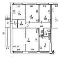 Sample business plan of a dental office
 Five best business ideas that brought millions What business to open so as not to go bankrupt