The history of steam turbines presentation. Presentation "the history of the invention of the steam turbine". Efficiency of heat engines
A steam turbine (fr. Turbine from Latin turbo vortex, rotation) is a continuous heat engine, in the blade apparatus of which the potential energy of compressed and heated water vapor is converted into kinetic energy, which in turn performs mechanical work on the shaft. water parakinetic mechanical work

STEAM TURBINE, turbine converting thermal energy steam into mechanical work. The flow of water vapor enters through the guide vanes on the curved blades fixed around the circumference of the rotor, and, acting on them, drives the rotor into rotation. Unlike a piston steam engine, a steam turbine uses not potential, but kinetic energy of steam.

Attempts to create steam turbines have been made for a very long time. Known is the description of a primitive steam turbine made by Heron of Alexandria (1st century BC). However, only at the end of the 19th century, when thermodynamics, mechanical engineering and metallurgy reached a sufficient level, Laval (Sweden) and Parsons (Great Britain) independently created industrially suitable steam turbines.

Laval applied the expansion of steam in conical fixed nozzles in one step from the initial to the final pressure and directed the resulting jet (with a supersonic outflow velocity) onto one row of rotor blades mounted on a disk. Steam turbines operating on this principle are called active turbines.

Parsons created a multistage jet steam turbine, in which the expansion of steam was carried out in a large number of successive stages, not only in the channels of the stationary (guide) blades, but also between the movable (working) blades. The steam turbine turned out to be a very convenient engine for driving rotary mechanisms (generators of electric current, pumps, blowers) and ship propellers; it was faster, more compact, lighter, more economical and more balanced than the piston steam engine.

abstract
on the topic:
"Steam turbines as the main engine in thermal power plants"
The history of the development of steam turbines
Imagine a closed metal vessel (boiler) partially filled with water. If you light a fire under it, then the water will begin to heat up, and then boil, turning into steam. The pressure inside the boiler will rise, and if its walls are not strong enough, it may even explode. This shows that the steam has accumulated a reserve of energy, which finally manifested itself as an explosion. Can't steam be forced to do some useful work? This question has occupied scientists for a very long time. The history of science and technology knows many interesting inventions in which man tried to use the energy of steam. Some of these inventions were useful, others were just clever toys, but at least two of these inventions must be called great; they characterize entire epochs in the development of science and technology. These great inventions are the steam engine and the steam turbine. The steam engine, which was used industrially in the second half of the 18th century, revolutionized technology. It quickly became the main engine used in industry and transportation. But at the end of the 19th and beginning of the 20th centuries. the attainable power and speed of the steam engine were no longer sufficient.
There was a need for the construction of large power plants, for which a powerful and high-speed engine was needed. The steam turbine became such an engine, which can be built for enormous power at a high speed. The steam turbine quickly displaced the steam engine from power plants and large steamers.
The history of the creation and improvement of the steam turbine, like any major invention, is associated with the names of many people. Moreover, as is usually the case, the basic principle of operation of the turbine was known long before the level of science and technology made it possible to build a turbine.
The principle of operation of a steam engine is to use the elastic properties of steam. Steam periodically enters the cylinder and, expanding, performs work moving the piston. The principle of operation of a steam turbine is different. Here the steam expands and the potential energy stored in the boiler is converted into high-speed (kinetic) energy. In turn, the kinetic energy of the steam jet is converted into mechanical energy of the turbine wheel rotation.
The history of the development of the turbine begins with the ball of Heron of Alexandria and the wheel of Branck. The possibility of using steam energy to obtain mechanical motion was noted by the famous Greek scientist Heron of Alexandria more than 2000 years ago. He built a device called Heron's ball (Fig. 1).
The ball could rotate freely in two supports made of tubes. Through these supports, steam from the boiler entered the ball and then exited into the atmosphere through two pipes bent at right angles. The ball rotated under the action of reactive forces arising from the outflow of steam jets.
Another project is described in the work of the Italian scholar Giovani Branca (1629). A tube is inserted into the upper part of the boiler (fig. 2).
Since the steam pressure inside the boiler is greater than Atmosphere pressure air around the boiler, the steam rushes out through the tube.
From the free end of the tube, a jet of steam hits and, falling on the blades of the wheel, makes it rotate.
Heron's model and Branck's wheel were not engines, but they already indicated possible ways of obtaining mechanical motion due to the energy of the driving steam.
There is a difference in the principles of action of Heron's ball and Branck's wheel. Heron's ball, as already mentioned, rotates under the influence of reactive forces. These are the same forces that push the rocket. It is known from mechanics that a jet pushed out of a vessel under the action of pressure, for its part, presses on the vessel in the direction opposite to the direction of outflow. This is obvious on the basis of Newton's third law, according to which the force pushing out the jet must be equal and opposite in direction to the force of the reaction of the jet on the vessel.
In a Branck turbine, the potential energy of the steam first converts into the kinetic energy of the jet beating from the tube. Then, when the jet hits the wheel blades, part of the kinetic energy of the steam is converted into mechanical energy of the wheel rotation.
If Heron's ball moves by reactive forces, then the so-called active principle is used in Branck's turbine, since the wheel draws energy from an active jet.
The greatest shift in the design of the steam turbine and its further development was outlined at the end of the nineteenth century, when in Sweden, Ing. Gustav Laval and Charles Parsons in England independently began to work on the creation and improvement of the steam turbine. The results achieved by them allowed the steam turbine to eventually become the main type of engine for driving electric current generators and to be widely used as an engine for civil and military ships. In the Laval steam turbine, created in 1883, steam enters one or more parallel connected nozzles, acquires a significant speed in them and is directed to the rotor blades located on the rim of the disk sitting on the turbine shaft, and forming a lattice of working channels.
The forces caused by the rotation of the steam jet in the channels of the working grate rotate the disk and the associated turbine shaft. A distinctive feature of this turbine is that the expansion of steam in the nozzles from the initial to the final pressure occurs in one stage, which leads to very high steam flow rates. The transformation of the kinetic energy of steam into mechanical energy occurs without further expansion of the steam only due to a change in the direction of flow in the blade channels.
Turbines built according to this principle, i.e. turbines, in which the entire process of steam expansion and the associated acceleration of steam flow occurs in stationary nozzles, are called active turbines.
In the development of active single-stage turbines, a number of difficult issues were resolved, which was extremely important for the further development of steam turbines. Expanding nozzles were used, which allow a high degree of expansion of the steam and allow achieving high velocities of the steam flow (1200-1500 m / s). To better exploit the high flow rates of steam, Laval developed a disc design of equal resistance allowing operation at high peripheral speeds (350 m / s). Finally, the single-stage active turbine used such high speeds (up to 32,000 rpm), which were much higher than those of the engines common at that time. This led to the invention of a flexible shaft, the frequency of free vibrations of which is less than the frequency of the disturbing forces at the operating speed.
Despite a number of new design solutions used in single-stage active turbines, their efficiency was low. In addition, the need to use a gear transmission to reduce the number of revolutions of the drive shaft to the level of the number of revolutions of the driven machine also slowed down the development of single-stage turbines and in particular the increase in their power at that time. Therefore, Laval turbines, having received considerable distribution at the beginning of the development of turbine construction as units of low power (up to 500 kW), later gave way to other types of turbines.
The steam turbine, proposed in 1884 by Parsons, is fundamentally different from the Laval turbine. The expansion of steam in it is carried out not in one nozzle group, but in a number of successive stages, each of which consists of stationary guide vanes (nozzle grids) and rotating blades.
The guide vanes are fixed in a stationary turbine casing, the rotor blades are arranged in rows on the drum. In each stage of such a turbine, a pressure drop is triggered, which is only a small fraction of the total pressure drop between the live steam pressure and the pressure of the steam leaving the turbine. Thus, it turned out to be possible to operate with low steam flow rates in each stage and with lower peripheral speeds of the rotor blades than in the Laval turbine. In addition, the expansion of steam in the stages of the Parsons turbine occurs not only in the nozzle, but also in the working grate. Therefore, forces are transferred to the rotor blades, caused not only by the change in the direction of the steam flow, but also by the acceleration of steam within the working grate, causing a reactive force on the rotor blades of the turbine.
Turbine stages, in which steam expansion and the associated acceleration of steam flow in the channels of the rotor blades are used, are called reactive stages. Thus, shown in Fig. Turbine 4 was a typical representative of multistage jet steam turbines.
The principle of sequential switching of stages, in each of which only a part of the available thermal difference is used, proved to be very fruitful for the subsequent development of steam turbines. It made it possible to achieve high efficiency in the turbine at moderate speeds of the turbine rotor, allowing direct connection of the turbine shaft with the shaft of the electric current generator. The same principle made it possible to produce turbines of very high power, reaching several tens and even hundreds of thousands of kilowatts in one unit.
Multistage jet turbines are now widely used, both in stationary installations and in the fleet.
The development of active steam turbines also followed the path of successive expansion of steam not in one, but in a number of stages located one after the other. In these turbines, a number of disks, mounted on a common shaft, are separated by partitions, called diaphragms, in which fixed nozzle grids are located. In each of the stages constructed in this way, steam expansion occurs within a part of the total available heat drop. In the working grids, only the transformation of the kinetic energy of the steam flow occurs without additional expansion of the steam in the channels of the working blades. Active multistage turbines are widely used in stationary installations, they are also used as marine engines.
Along with turbines in which steam moves in the direction of the turbine shaft axis (axial), radial turbine designs have been created in which steam flows in a plane perpendicular to the turbine axis. Of the latter, the most interesting is the radial turbine, proposed in 1912 in Sweden by the Jungström brothers.
Rice. Schematic drawing of the Jungstrom radial turbine:
1,2 - turbine disks; 3 - live steam lines; 4, 5 - turbine shafts; 6, 7 - blades of intermediate stages
On the lateral surfaces of the disks 1 and 2, the blades of the jet stages are located in rings of gradually increasing diameter. Steam is supplied to the turbine through pipes 3 and then through the holes in the discs 1 and 2 is directed to the central chamber. From here, it flows to the periphery through the channels of the blades 6 and 7, fixed on both discs. Unlike conventional designs, the Jungstrom turbine does not have fixed nozzle grids or guide vanes. Both discs rotate in opposite directions, so that the power developed by the turbine must be transmitted by shafts 4 and 5. The principle of counter-rotating rotors makes the turbine very compact and economical.
PAGE_BREAK--
Since the early 1990s, steam turbine development has progressed at an extremely rapid pace. This development was largely determined by the equally rapid parallel development of electrical machines and the widespread adoption of electrical energy in the industry. The efficiency of the steam turbine and its power in one unit have reached high values. In terms of their power, the turbines far surpassed the power of all other types of engines without exception. There are turbines with a capacity of 500 MW associated with an electric current generator, and the possibility of making even more powerful units, at least up to 1000 MW, has been proven.
In the development of steam turbine construction, several stages can be noted, which affected the constructive performance of turbines built in different periods of time.
In the period before the imperialist war of 1914, the level of knowledge in the field of the work of metals at high temperatures was insufficient for the use of steam at high pressures and temperatures. Therefore, until 1914, steam turbines were built mainly for operation with steam of moderate pressure (12-16 bar), with temperatures up to 350 ° C.
With regard to increasing the capacity of a single unit, great success was achieved already in the initial period of the development of steam turbines.
In 1915, the capacity of individual turbines already reached 20 MW. In the post-war period, starting from 1918–1919, the trend towards an increase in power continues to persist. However, in the future, the turbine designers pursued the task of increasing not only the power of the unit, but also the number of revolutions of high-power turbines when they are performed with one electric current generator.
The most powerful high-speed turbine in the world at one time (1937) was the turbine of the Leningrad Metal Plant, built at 100 MW at 3000 rpm.
In the period before the imperialist war of 1914, turbine factories in most cases produced turbines with a limited number of stages located in one turbine housing. This allowed the turbine to be made very compact and relatively cheap. After the war of 1914, the tension in the fuel supply experienced by most countries demanded an all-round increase in the efficiency of turbine units.
It was found that the maximum efficiency of the turbine can be achieved by applying small thermal drops in each stage of the turbine and, accordingly, building turbines with a large number of stages. In connection with this trend, turbine designs arose that, even with moderate parameters of live steam, had an extremely large number of stages, reaching 50 - 60.
The large number of stages made it necessary to create turbines with multiple casings, even when the turbine was connected to a single electric generator.
Thus, two- and three-casing turbines began to spread, which, while being highly economical, were very expensive and cumbersome.
In the subsequent development of turbine engineering in this matter, there was also a certain deviation towards simplifying the design of the turbine and reducing the number of its stages. Turbines with a capacity of up to 50 MW at 3000 rpm were built for quite a long time only as double-hulled ones. The newest condensing turbines of this capacity, produced by advanced factories, are built in single-casing.
Simultaneously with the design improvements of moderate-pressure turbines (20-30 bar), more economical high-pressure installations, reaching 120-170 bar, began to spread in the period from 1920 to 1940.
The use of high-parameter steam, which significantly increases the efficiency of the turbine plant, required new solutions in the design of steam turbines. Significant success has been achieved in the use of alloy steels with a sufficiently high yield stress and low creep rates at temperatures of 500 - 550 ° C.
Along with the development of condensing turbines, already at the beginning of this century, installations for the combined generation of electricity and heat began to be used, which required the construction of turbines with back pressure and intermediate steam extraction. The first turbine with constant bleed steam pressure control was built in 1907.
The conditions of the capitalist economy, however, prevent the use of all the advantages of combined heat and power generation. Indeed, the capacity of heat consumption abroad is in most cases limited by the consumption of the enterprise where the turbine is installed. Therefore, turbines that allow the use of exhaust steam heat are most often built abroad for small capacities (up to 10 - 12 MW) and are designed to provide only individual heat and electricity. industrial enterprise... It is characteristic that the largest (25 MW, and then 50 and 100 MW) turbines with steam extraction were built in the Soviet Union, since the planned development of the national economy creates favorable conditions for combined heat and power generation.
In the post-war period, in all technically developed European countries, as well as in the United States, there is an ever-accelerating development of energy, which leads to an ever-increasing increase in the capacity of energy units. At the same time, there is a tendency to use increasingly higher initial steam parameters.
Condensing single-shaft turbines reach a capacity of 500 - 800 MW, and with a two-shaft version, plants with a capacity of 1000 MW have already been built.
As the capacity increased, it was also expedient to increase the initial steam parameters, which were sequentially selected at the level of 90, 130, 170, 250 and, finally, 350 bar, while the initial temperatures also increased, which amounted to 500, 535, 565, 590, and in some cases up to 650 ° C. It should be borne in mind that at temperatures exceeding 565 ° C, it is necessary to use very expensive and less studied steels of the austenitic class. This has led to the fact that in recent years there has been a tendency towards some retreat to the temperature range, which excludes the need to use austenitic steels, i.e. temperatures at 540 ° C.
The successes achieved in 1915-1920 were of great importance for the development of low-power turbines, and especially for the development of ship steam turbines. in the field of construction of reducers. Until that time, ship turbines were run at a number of revolutions equal to the number of revolutions of the propellers, i.e. 300 - 500 rpm, which reduced the efficiency of the installation and led to large dimensions and weights of the turbines.
Since the time when complete reliability and high efficiency have been achieved in the operation of gear reducers, marine turbines are supplied with gear drives and run at an increased speed, which corresponds to the most favorable conditions for the operation of the turbine.
For stationary turbines of low power, it has also turned out to be advisable to use a gear transmission between the turbine and the generator. The greatest number of revolutions possible with a direct connection of the shafts of the turbine and the 50-period alternating current generator is 3000 rpm. For capacities below 2.5 MW, this speed is disadvantageous for a condensing turbine. With the development of gearbox engineering, it became possible to execute turbines at higher speeds (5000–10000 rpm), which made it possible to increase the efficiency of low-power turbines, and most importantly, to reduce their size and simplify the design.
Typical design of a modern steam turbine
When designing a steam turbine, a number of requirements are taken into account:
- reliability and trouble-free operation;
- high thermal efficiency;
- high uniformity of rotation and high speed, allowing the use of high-speed electric generators with the possibility of their direct connection with the engine shaft;
- the possibility of obtaining any required unit power in the engine;
- the ability to automate the operation of the entire installation;
- ease of maintenance of the installation;
- compactness of the engine and its relative cheapness;
- the ability to work in a closed loop.
Let us consider the design of a typical modern active turbine using the example of a high-pressure turbine of the Leningrad Metal Plant. The power of this turbine is 50 thousand kW at 3000 rpm. The turbine operates with steam with an initial pressure of 88 bar at a temperature of 535 ° C.
The first 19 discs of moderate diameter are made in one piece with the turbine shaft. The next three discs are fitted with an interference fit on the shaft. On the rims of each disc, there are working blades. The discs are separated by fixed intermediate diaphragms. In each diaphragm there is a fixed nozzle lattice, in which the steam flow is accelerated and acquires the necessary direction to enter the channels of the working lattice formed by the rotor blades. The gradual increase from step to step in the height of the nozzle grids and rotor blades is explained by the fact that as the steam expands, its volume increases. This requires a gradual increase in the flow area of the flow path. The nozzle grids of the first control stage are fixed in the steam supply pipes, which are welded into the turbine housing. Steam is supplied to the nozzles of the first control stage through four control valves, two of which are located on the upper half of the body, and two - on the sides of the lower part of the body. The part of the body enclosing the high-pressure stages is made in the form of a steel casting. Steps low pressure are located in the welded part of the body. The turbine outlet is also welded from sheet steel and welded to the condenser. By cooling the steam spent in the turbine, the pressure in the condenser is maintained below atmospheric pressure. Typically this pressure is 0.03 - 0.06 bar. Several branch pipes are provided in the turbine housing for extracting steam from the intermediate stages of the turbine. These extractions are used to heat the feed water supplied to the steam boiler.
When the load changes, it turns out to be necessary to change the flow rate of the steam flowing through the turbine. This is achieved by appropriate opening of the control valves. Due to the fact that the valves are closed and opened in sequence, part of the steam passing through the fully open valves is not crushed and enters the first stage nozzles at full initial pressure. Only that fraction of steam that passes through the partially open valve is throttled in the valve and approaches its nozzle group with reduced pressure. The method of controlling the steam inlet into the turbine, in which steam access to the nozzle groups is opened sequentially, is called nozzle steam distribution. The first stage, which receives steam from a different number of nozzle groups, depending on the turbine load, is called a control stage. In addition to this method of steam distribution, there is also a throttling method for supplying steam, characterized in that the entire amount of steam supplied to the turbine passes through a common control valve. At partial turbine loads, the steam is crumpled due to the partial closure of the throttle control valve.
Continuation
--PAGE_BREAK--
The turbine shaft rests on two bearings that support the weight of the rotor. The front bearing in the turbine simultaneously fixes the axial position of the rotor in relation to the stator and absorbs the axial forces acting on the rotor. Thus, the front bearing is a combined thrust bearing. Its thrust part is built on the principle of Mitchell's segment bearing.
Where the shaft passes through the turbine housing, there are seals called shaft end seals. The front shaft seal is used to reduce steam leakage from the turbine housing into the machine room. The rear seal prevents atmospheric air from being sucked into the exhaust pipe and turbine condenser. Air suction into the condenser would increase the pressure in it and reduce the efficiency of the turbine operation. To prevent air from leaking into the condenser, low pressure steam is supplied to the rear seal. In places where the shaft passes through the central holes of the intermediate diaphragms, intermediate seals are installed to prevent steam from flowing from one stage to another, bypassing the nozzle grilles of the stage.
The right end of the turbine shaft is connected by a coupling to the generator rotor, one of the bearings of which is located on the housing of the turbine exhaust pipe.
The front end of the turbine shaft is connected by a flexible coupling to the shaft of a two-way centrifugal oil pump, which is supported by a suction pipe on a lug in the front bearing housing. Oil is supplied to the suction cavity of the pump under a slight overpressure by means of an injector.
The oil pump supplies oil to the controls of the regulation system (at 20 bar pressure) and, using an injector, supplies oil to the bearings of the generator and turbine (at 0.5 bar pressure). At the end of the pump shaft there is a high-speed elastic speed regulator that controls the spools of the control system.
In the transverse bores of the front end of the turbine shaft, there are two strikers of the safety switch, which causes a complete cessation of steam supply to the turbine in the event of an increase in its rotation speed by 10 - 12%.
In modern high-power turbines, a special barring device is provided, with which you can slowly rotate the shaft of an idle turbine. The barring device consists of an electric motor connected to a worm gear.
The worm, with the help of a worm wheel, rotates an intermediate roller, on which, on a screw key, the drive gear is located. The latter can be displaced in the axial direction and mesh with a large gear, mounted on a half-coupling, connecting the turbine shaft and the generator shaft. When the turbine is started, when its shaft is accelerated by steam, the drive gear turns along the helical key and automatically disengages from the gear that is sitting on the turbine half-coupling.
The turbine housing and bearing housings are horizontally split at the level of the turbine shaft axis. In order to disassemble the turbine, it is necessary to loosen the joint of the flanges of the horizontal joint of the turbine housing and the bearing housings. The housing covers can then be lifted.
Modern turbines for driving electric generators are designed to operate at a constant speed. Keeping the speed constant is ensured by automatic regulation.
The regulators are controlled by oil. Therefore, the regulation system is usually combined with a lubrication system.
A significant amount of heat is generated in the turbine bearings, which must be removed so that the bearing temperature does not exceed the permissible value (about 60 ° C). Heat dissipation from the bearing is provided by a circulating lubrication system, in which the oil not only reduces friction by creating a film between the shaft and bearing shells, but also serves to cool the bearing. The heated oil leaving the bearing is reused for lubrication after cooling.
The rotor parts of a steam turbine (blades, discs), even at normal turbine speed, are subject to high stresses caused by centrifugal forces. An increase in the number of revolutions of the turbine in excess of the operating speed leads to such an increase in centrifugal forces, which can cause a turbine failure. In order to protect the turbine from an unacceptable increase in the number of revolutions in the event of a malfunction of the main control system, modern turbines are equipped with safety switches. The safety switch is usually located on the turbine shaft. If the turbine speed exceeds the normal speed by 10-12%, the safety switch causes the turbine start valve to quickly close and stop.
Features of large steam turbines
An increase in the parameters of steam and the unit capacity of the units, as well as the introduction of intermediate superheating of steam, led to the use of turbines with a large number of cylinders. An increase in steam consumption, on the one hand, increases the efficiency of the first stages of the turbine due to an increase in the heights of the blades in the high-pressure cylinder (HPC), and on the other hand, complicates the design of the last stages. The desire to increase the thermal efficiency of the cycle leads to a decrease in the absolute pressure in the condenser to 0.03 - 0.035 bar, which significantly increases the volumetric steam flow in the last stage. To obtain the minimum losses with the output kinetic energy, a possibly large area swept by the blades is required. The required value is achieved, firstly, by increasing the length of the blade and the diameter of the last stage, and secondly, by increasing the number of parallel steam flows in the low pressure part (LPP). For this purpose, it is also possible to use two-tier blades.
The maximum blade length is largely determined by strength considerations. At the same time, the problem of creating long blades is not only strength but also aerodynamic. With an increase in the relative length of the blades, the risk of flow separation in the root region increases. This is a serious obstacle to further increasing the relative length of the blades. Modern methods design allows avoiding flow separation at design conditions. At partial loads, flow separations occur in such stages, covering a wide area at the root of the wheel. These phenomena reduce the efficiency of the last stages, and also have an adverse effect on the vibration strength of the wheel.
The number of steam outlets for very powerful units already reaches eight. The issue of choosing the number of unit shafts is associated with obtaining the maximum exit area. A single-shaft unit is simpler and usually cheaper than a twin-shaft unit. At the same time, the twin-shaft unit allows you to apply different speeds of rotation of both shafts. Reducing the rotation speed of the LPP allows you to increase the input area of the last stage at the same level of permissible voltages and reduce losses with the output speed.
Twin-shaft units are widely used abroad. This applies not only to very powerful plants of the conventional type, but also to nuclear plants operating at relatively low steam parameters and having huge volumetric flows in the last stages of the turbines. In addition, in a number of countries (USA, Latin America, etc.), a critical current frequency of 60 Hz is used, which significantly complicates the task of creating long blades with high speed rotation (3600 rpm).
There is no consensus on which of the options (single-shaft or two-shaft) to give preference to. In the late 1950s, leading experts from foreign firms Brown-Boveri, General Electric and Siemens considered the maximum economically viable capacity of a single-shaft unit 400–500 MW. The last decade has markedly changed the trend of most factories and firms in this matter. Domestic and foreign factories and firms design and manufacture single-shaft turbines, the capacities of which significantly exceed the values that were considered "limiting" a few years ago. (Currently, turbines with a capacity of 800 and 1200 MW - LMZ, 765 MW - General Electric, 800 - 1000 MW - Siemens, 600 MW - companies from England, France, Italy, etc. are being manufactured and designed). The West German firm Siemens, on the basis of technical and economic calculations, currently considers the production of twin-shaft units up to 1000 MW unpromising. At the same time, a large number of twin-shaft units are being produced by American and Western European firms. The most powerful units (800 - 1300 MW) are currently being manufactured abroad as twin-shaft ones. Single-shaft turbines with a capacity of up to 800 MW were produced in the USSR. Currently, LMZ and KhTGZ are producing more powerful single-shaft machines.
With an increase in the initial parameters of steam and the unit capacity of the units, the question of choosing the type of steam distribution of steam turbines has become urgent again. This problem cannot be solved in isolation from the question of the expected operating modes of the turbine. Throttle steam distribution allows for the highest efficiency in the design mode. As shown by the calculations performed in LPI together with LMZ, the use of throttle steam distribution for the K-200-130 turbine instead of the nozzle one with the replacement of the control stage by three pressure stages reduces the specific heat consumption in the power plant's turbine room at the nominal mode by about 0.3%, and for the turbine K-300-240 - by 0.4%. This increase in efficiency is tantamount to an increase in the efficiency of the control stage by about 2%.
The nozzle steam distribution, yielding to the throttle at the nominal mode, surpasses it in efficiency at partial loads (in the examples considered, at loads less than 90% of the nominal). One of the significant disadvantages of the nozzle steam distribution at high steam parameters is that due to the different throttling of steam in the control valves with their unequal opening, the temperatures of the steam flows passing through these valves can differ significantly. So, for example, with initial parameters of 400 bar, 650 ° C, the steam temperature behind the valve, open by 10%, turns out to be 180 ° C lower than the steam temperature behind the fully open valves.
Such a non-uniform flow and the associated uneven heating of the turbine stator can cause significant thermal stresses and casing warpage. To eliminate the unevenness of the steam parameters in front of different groups of nozzles, the simultaneous inlet of steam into several groups of nozzles is used; in this case, the nozzle steam distribution approaches the throttle one, and the difference in the efficiency of the partial modes between them decreases.
At the same time, the power of the regulating stages of the largest steam turbines has reached an extraordinary value. For example, in the LMZ K-800-240 turbine, its capacity is about 50,000 kW. Designing the rotor blades of such a stage for unsteady flow conditions becomes extremely difficult. For these reasons, for units with a capacity of 1000 MW and above, preference is given to throttling steam distribution.
A significant advantage of throttling steam distribution with full steam supply is the improvement of the vibration characteristics of the first stage vane. Throttle steam distribution with full steam supply is becoming more widely used for powerful steam turbines. With this steam distribution, turbines with a capacity of 1000 and 1150 MW are made in the USA. Throttle steam distribution has a 1300 MW turbine designed by the Swiss company Brown-Boveri for the USA. Throttle steam distribution is also envisaged in new projects of turbines with a capacity of 1200-1600 MW LMZ.
Continuation
--PAGE_BREAK--
Possibilities for increasing the power of a steam turbine
The increase in turbine power up to 1600 MW and even up to 2000 MW was envisaged in a unified row, in which the head turbine K-1200–240. This turbine, under certain conditions, can develop a capacity of up to 1400 MW. At an elevated cooling water temperature and pk> 4.5 kPa, on the basis of the existing LPC, the turbine power can be increased to 1600 MW. The problem of a steam generator in the form of a monoblock or, possibly, a double block (based on the existing boiler for the K-800-240 unit) is also being solved. It should also be borne in mind that the temperature of the cooling water for most GRESs will gradually increase and that over time, turbines for pk = 6.5 kPa will be used, and this will significantly increase their capacity.
It is advisable to choose a fundamentally new power range based on the principle of doubling the power, i.e. set the task of creating blocks of 2500 - 3000 MW. Solving this problem will require extensive scientific research and design work as well as pre-production in the field of turbines, boilers and generators. These works will take a long time to complete. For such a major step, it is necessary to revise both the steam parameters and the fundamental structure of the power plant. Let us consider only the possibilities of further growth of turbine power without fundamental changes in the thermal scheme and steam parameters.
At present, there are preliminary designs for turbines with a capacity of 2000-2400 MW, which make it possible to judge their prospects.
When solving this problem, the choice of the rotational speed of the turbine generator is a central issue. With a capacity of over 2000 MW, low-speed turbines can compete with high-speed ones in terms of general economic indicators and reliability. The efficiency of the HPC of a low-speed turbine is approximately the same as that of a high-speed turbine, since the latter already requires a two-flow HPC and, therefore, there is no noticeable gain from increasing the length of the blades. These considerations apply even more to DCS. In a low-speed turbine, the LPC can, in principle, due to lower output losses, have a higher efficiency than in a high-speed turbine, or the number of cylinders can be significantly reduced in it. The solution to the problem of a high-speed turbine by increasing the number of LPC leads to a too long shafting, in which vibrations are easily excited. If we limit the number of cylinders, then the only way to increase power is to increase the area S swept by the blades of the last stage. This area is proportional to d2l2 or u2l2. For reasons of flow aerodynamics, the fan-like factor dl is limited (currently at least 2.5). Taking this coefficient constant, we find that for a given rotation frequency S ~ u2. For these conditions, at a given pk, the steam flow rate of the LPC and, consequently, the limiting power of the turbine are proportional to the square of the peripheral speed of the last RK. Already now, in the K-1200–240 LMZ turbine, u2 = 471 m / s (u2 "= 660 m / s), and at the periphery, the peripheral speed is much higher than the sound one. Still, the possibility of its further increase is not excluded.
If the loss of the output kinetic energy is maintained and at the same time the peripheral speed is increased, then small angles β2 * are obtained, which can cause difficulties in designing the meridional section of the flow path of the last stages and a strong blade at the periphery of the RK. In such cases, the question arises of increasing the output speed, despite the increase in the output loss. This, however, is possible only up to a certain limit, since, due to large losses, it is impossible to admit movement at supersonic speeds in the outlet pipes having an unfavorable aerodynamic shape.
When designing high-speed turbines with a capacity of 2500–3000 MW, there are also difficulties in the design of HPC and especially HPC due to large blade lengths and rotor sizes.
Twin-shaft high-speed turbines open the way to a significant increase in the "limiting power" while maintaining high efficiency of the installation due to the increase in the number of unified LPC and MPC. The problem of two-tiered steps also deserves special attention.
Due to the difficulties in designing a high-speed turbine with a capacity of 2000 MW and more, a low-speed turbine is being proposed as an alternative. The main disadvantages of the latter: the large mass and size of the main parts, which worsens the thermal state of the cylinders, and also creates difficulties in transportation, installation and repair, increases the cost construction works on ES. However, there is a limit of the turbine power, beyond which, with the available technical means a slow-speed turbine has an advantage over a high-speed one. For a comparative assessment of these types of turbines, let us consider some of their design options.
Design options for a 2000 MW turbine at n = 3000 rpm. At CKTI, research projects were carried out on a high-speed turbine K-2000–240 / 3000 for steam parameters of 23.5 MPa and 838/838 K. This project was based on the currently used steam parameters. The temperature of the cooling water was taken as 293 and 298 K. The thermal circuit of the unit was considered the same as in modern turbines of the K-1200-240 type.
By the time of the project implementation the mechanical properties of the materials were supposed to be 15 - 20% higher than at the present time. It was also assumed that forgings from chromium stainless steels weighing 60–100 tons for high and medium pressure rotors would be mastered and that rotors without central holes would be manufactured. It was assumed that it would be possible to use forgings made of maraging stainless steels with a yield point of 1200–1400 MPa and a mass of up to 15 tons. For titanium rotor blades, a yield point of up to 900 MPa was chosen. Basically, the project was focused on the already achieved level of mechanical properties of the applied turbine materials and on the proven safety margins.
The main features of the project: a small number of stages in single-flow high-pressure pumps and high-pressure pumps due to high peripheral speeds (rotor diameters at root sections d / = 1400 mm); placement in one cylinder of CVD and CSD; use for the last stage of the LPC of a blade with a length of l2 = 1200 mm and a diameter of d2 = 3000 mm (ΣS = 90.4 m2); back pressure pк = 5.2 kPa; the separation pressure between the cylinders is 0.7 MPa. Under these conditions, the turbine turned out to be a five-cylinder with eight outlets from the LPC with a total of 49 stages and with a central HPP.
Total consumption steam G = 6500 t / h. Due to the high back pressure, a large specific steam consumption at each outlet of the LPC was obtained - 45 t / (m2 h), while in the K-1200-240 turbine it was about 32 t / (m2 h) at pk ~ 3.6 kPa. The output kinetic energy is hC2 = 43 kJ / kg (~ 10 kcal / kg) and MC2g = 0.85. This output loss is extremely high. The internal efficiency of the CVD and CSD can be taken as 0.89, and for low pressure - 0.83. HPP capacity is about 700 MW, HPP capacity is about 600 MW and LPP capacity is 8x10⁵ MW (total internal capacity is 2140 MW). CVD and CSD are unloaded with dummies from axial pressure.
The combined HPC-HPC is located in the center of the unit, and on both sides of it there are 2 LPCs. Compared to conventional cylinder arrangements, this reduces the relative thermal expansion and reduces the journal diameter of the thrust bearing placed on the HPC side, which makes it possible to achieve an acceptable peripheral speed in this bearing. In addition, the size of the bypass pipes is reduced due to the branching of the flow immediately after the PSH. The low-frequency vibration characteristic of the RVD is also improved, since it does not have a free journal on the side of the front bearing.
Compared to the K-1200-240 turbine, the rotor necks are subjected to greater forces (calculated for four times the torque in the event of a short circuit). For them, rotor inserts with flange connections are used, made of special durable material(maraging steel). The diameters of the necks do not exceed 600 mm.
The tension of the housings and stator elements does not exceed the permissible values in already operating turbines. The blades, tail joints (herringbone type), the rotor body are extremely stressed, especially in the high temperature area in the CSD, i.e. in the zone of the first stage; the rotor can be made of steel P2M with a margin of yield strength of 1.25. The calculation was carried out on the assumption of operation for 100,000 hours. The production of forgings from chromium stainless steels will increase the durability of the rotors.
The length of the turbine is 49 m, it is only slightly longer than the length of the K-1200-240 turbine.
New options for connecting the LPC with the condenser and the foundation have been developed: the outer casing is a thin-walled shell, and it does not serve as a base for centering the inner casing, connected through the frame directly to the foundation.
The specific metal consumption of the turbine without a condenser, according to preliminary calculations, is about 1.3 kg / kW versus 1.6 kg / kW for K-1200–240 (at pk = 4 kPa).
Design options for a turbine with a capacity of more than 2000 MW at n = 1500 rpm. For nuclear power plants, turbines with a capacity of 500 and 1000 MW are produced, operating at 1500 rpm. Huge expenditures have been made associated with the manufacture of the largest products for this purpose, which necessitated not only the construction of new turbine shops, but also the restructuring of the metallurgical industry serving turbine plants. Thanks to this contribution to the industry, it is now possible to solve the problem of further development of heavy-duty turbines on a broad basis using both high-speed and low-speed turbines, depending on their economic indicators and the degree of reliability.
At the CKTI were performed under the leadership of L.D. Frenkel design developments turbine with a capacity of 2000 MW at 1500 rpm, which was considered together with a high-speed turbine as an alternative solution. The 2000 MW capacity is close to the border of the high speed turbine, and this makes the comparison of projects interesting, although this condition is not in favor of the low speed turbine option.
Initial steam parameters 23.5 MPa, 833/838 K: back pressure 5.9 kPa. The final temperature of the feed water tp.w = 543 K. The flow part is located in a single-flow HPC (12 stages) with a capacity of about 710 MW, a two-flow HPC (2x8 stages) and in three LPCs (2x6 stages) with a capacity of 2x127 MW. The total number of stages is 64. The stage with a blade l2 = 1400 mm, d2 = 4100 mm, d1 = 2.93 and S = 18 m2 served as the basis for designing the flow path of the LPC. The specific steam consumption of the last RK is about 33 t / (m2 h). The pressure behind the HPC is 3.6 MPa, behind the HPC 0.37 MPa.
The efficiency of the c.p. cvd and csd according to calculations is about 0.89, and for cnd 0.85. Their high values are achieved mainly due to lower output losses after each last stage in the cylinders, especially in the LPC, where at the design mode hС2 –20 kJ / kg, which is approximately two times lower than these losses in a high-speed turbine. Under these conditions, the specific heat consumption is only slightly less than for a steam turbine with a K-1200-240 turbine.
A difficult task is the design of high and medium pressure rotors in which local temperatures exceed 803 K and stresses in the bore reach 170 MPa. In the hottest places, the rotor is cooled by steam taken before the first superheater. When cooling these places by 25 - 30 K, heat-resistant pearlitic steels can be used. The average diameters of the high pressure hoses are 1800–1970 mm with the length of the first and the last rotor blades approximately 100 and 300 mm, and the same dimensions of the RSD are 2315–2770 mm and the RL - 150 and 410 mm. Rotors of HPC and HPC are welded, drum type. RVD weighs about 65 tons, and RSD - about 110 tons.
Continuation
--PAGE_BREAK--
In the LPC, the last stage is comparatively little stressed. Its working blade is far from the limiting in size, the stresses in the root section are from bending with an average value of PAS σi = 23MPa (taking into account a pressure drop of 29 MPa). For a material with a yield point of σ0.2 ~ 640MPa, the safety factor in the rotor is kt ~ 2.8. All these voltages are significantly less than in high-speed turbines of the same power.
RND weight is 145 tons; nk = 2820 rpm. The total mass of the turbine is about 3100 tons. The length of the turbine is about 56.5 m.
Comparison of low-speed and high-speed turbines. The study of the projects of high-speed and low-speed turbines leads to the conclusion that the K-2000-240 turbine can be made of both types. In terms of efficiency, both types of turbines should not differ significantly.
Both turbines are designed with five cylinders. At the same time, the weight of the high-speed turbine (without the condenser) turned out to be less than the low-speed turbine by more than 20%. But a low-speed turbine can be made with the length of the last blades 1600 mm and even more at dl ~ 3, and then the swept area of the last RK will be 27 m2, which is 1.5 times larger than that adopted in the project and 2.4 times larger than the same area in a high-speed turbine with the last blade 1200 mm long. At the same time, the number of LPCs in a low-speed turbine will decrease, and it will become more competitive.
In the project, the low-speed turbine is about 6.5 m longer and somewhat wider than the high-speed one (the width is determined by the size of the LPC outlet pipe).
Among the positive factors of a low-speed turbine, we note: low circumferential speeds and stresses in the LPR, rigid and relatively heavy rotors. The latter facilitates the elimination of low frequency vibration. But nevertheless, these advantages cannot be recognized as decisive when considering a turbine with a capacity of 2000 MW. The advantages of a low-speed turbine could be revealed with a significantly higher power and with an optimal number and dimensions of the LPC.
Thus, the steam turbine is the main engine at thermal power plants and has a number of advantages over other types of engines:
- rotary principle of action;
- speed and the possibility of inconsistent connection with the generator shaft;
- high thermal efficiency, provided that high initial and low final parameters of steam are used;
- unlimited unit power;
- the ability to use any industrial type of fuel.
The disadvantages of steam turbines include:
- large dimensions and weight;
- high demands on steam purity;
- the need for large quantities of cooling water;
- the impossibility of creating a highly efficient low-power steam turbine.
Thermal cycles of thermal power plants operation.
In the first half of the 19th century. physicist and engineer Carnot was the first to consider an ideal reversible cycle, consisting of two isotherms and two adiabats (Fig. 6), and determined the thermal efficiency of the cycle.
Rice. 6 Karnot cycle in T-S-diagram
The working fluid expands isothermally with temperature /> = const from point 1 to point 2 when heat is supplied />, and from point 2 to point 3 - adiabatically, i.e. without supply and removal of heat. The temperature at the end of the expansion T2 is lower than the temperature T1. From the state at point 3, the body passes into the initial state at point 1, first along the isotherm T2 = const with heat removal />, and then along the adiabat (line 4–1).
In the T-S diagram, the area under the curve of a thermodynamic process is numerically equal to the amount of heat involved in it. The amount of supplied heat /> is numerically equal to the area of the rectangle />, and the rejected /> is equal to the area of the rectangle />. Therefore, the area of rectangle 1234 is numerically equal to the amount of heat converted into mechanical energy:
Consider the ideal Carnot cycle in the wet steam region.
At the end of the heat removal process in the Carnot cycle, t. D degree of dryness 0<1, поэтому в последующем процессе сжатия daдолжен сжиматься влажный пар от начального состояния />up to x = 0 (m. a). Since /> is determined by the change in the specific volume, the work expended on compression will be very large (the change in the specific volume is 3 orders of magnitude). Moreover, in order to increase the efficiency of the Carnot cycle, that is, to increase /> and decrease />, it is necessary to increase the initial pressure and decrease the final one, while the end point of the heat removal process, m. the compression will increase. In addition, since at the beginning of the compression process there is wet steam, and at the end of it, i.e., a saturated liquid, the compression process itself cannot be carried out either with the help of a compressor or with the help of a hydraulic pump. As a result of these features, the Carnot cycle was modified and received the name of the Rankine cycle. The changes consisted only in the fact that the process of heat removal is carried out until the complete condensation of the working fluid.
Continuation
--PAGE_BREAK--
Therefore, in the further compression process, it is not the wet vapor that is compressed, but the liquid. Since the change in volume with a change in pressure for a liquid is small, therefore, the work of compression in the Rankine cycle turns out to be much less than in the Carnot cycle, that is, de can be considered an isochore. And since the compression occurs under ideal conditions, that is, adiabatically, the de line is called an isochore or isentrope.
Consider the operation cycle of thermal power plants in the T-S-diagram.
When heat is supplied and removed, the phase state of the working fluid changes (liquid - vaporous - liquid). Heating of water in steam generator 1 to saturation temperature /> at pressure p (line 1–2), vaporization (line 2–3) in steam generator 1 and superheating of steam (line 3–4) in superheater 2 of the steam generator occur at p = const. The T-S diagram can be used to determine the phase state of 1 kg of the working fluid at any point in the cycle.
In the region of saturated vapor, the isobaric process (line 2–3) coincides with the isothermal process; vaporization occurs at constant pressure at a temperature Tp. Water enters the steam generator 1 with a heat content />, which is represented by an area of 1a0d. The amount of heat spent on heating water to the saturation (boiling) temperature is numerically equal to the area of 12 ba; for steam generation - an area of 23 wb; for steam superheating - an area of 34 guards. The total amount of heat /> transferred to the working fluid is numerically equal to the area of 1234 hectares. This is the amount of heat in the isobaric process of its supply
In an ideal turbine, steam expansion occurs along the isentrope (line 4–5). After the turbine, the steam enters the condenser, where it transfers heat to the cooling water, which enters a cold source (river, lake, etc.). The condensation process of the steam spent in the turbine is shown by line 5-1. The amount of heat given to the cold source is numerically equal to the area of 51 ar:
where /> kcal / kg in steam turbine installations operating in deep vacuum.
Steam condensation occurs at constant temperature /> and constant pressure /> kgf / cm, i.e. isobaric and isothermal processes coincide.
State and development prospects of domestic steam turbines.
Domestic power steam turbine construction has been at a high level for a long time. Turbines and other equipment of turbine plants (PTU) are designed and manufactured at Russian factories and two Ukrainian plants - Kharkov turbine (now Turboatom) and Sumy pumping. All the equipment of the power plants was made on its own, unlike, say, the USA and Japan, where imported equipment (in particular, steam turbine) is also used.
Our factories have created PTUs, turbines and their elements, many of which have not yet been surpassed abroad. In this regard, we can note the world's largest single-shaft turbine SKD LMZ K-1200-23.5 for driving a two-pole electric generator, which has been successfully operating at the Kostromskaya SDPP for more than 20 years. In general, in the Russian Federation the number of supercritical pressure turbines (SKP) is greater than in any other country: 100 condensing turbines. At the same time, almost all power engineering in Europe (except for the CIS countries), developing countries and, to a large extent, the United States, until recently, was focused on subcritical pressure p = 16.3 - 18 MPa. Abroad, at steam-power thermal power plants, such a deep design vacuum is rarely found as at our TPPs - at tcool.w = 12 C, although this significantly complicates the creation of powerful turbines.
Only in the countries of the former USSR were high-speed five-cylinder saturated steam turbines with a capacity of 500 and 750 MW produced by Turboatom and a capacity of 1000 MW LMZ operated for a long time. The scheme of these turbines - 2 LPCs on each side of the two-flow HPC; the complex multi-bearing shaft line has good vibration characteristics. Some domestic powerful NPP turbines, low-speed at 25 1 / s: turbines Ne> 500 MW Turbatom for double-circuit NPPs with VVER reactors.
Almost half of the power plants in the Russian Federation that use fossil fuels are CHP plants with economically and environmentally friendly combined heat and power generation. In total, outside the CIS countries there are not as many heating turbines as developed by TMZ and LMZ, there is no such variety of designs, schemes, capacities. The world's first cogeneration turbines SKD with a capacity of up to 300 MW (T-250 / 300–23.5 TMZ) were mastered in the early 70s. Nowadays, 22 such power units are in operation at the CHPP of the Russian Federation.
In our country, for the first time, systems of two-stage heating extractions, heat extractions of unregulated pressure were used. Now such systems are widely used both in our country and abroad, where in last years, including in Northwestern Europe, in the PRC, thermal power plants have become widespread, and in Denmark on coal-fired power units with a capacity of up to 400 MW and above. However, in this area, both in terms of parameters and in terms of efficiency, we began to lag behind, more and more supplying small units to our own CHPPs, which are ineffective and relatively expensive.
It is known that the most difficult element of a turbine is the last stage. An increase in its length (at the same rotational speed n) and an annular area Ω largely characterizes the technical level of a turbine plant or a company. One of the progressive ways to solve this problem (after about 5 years, each company switches to the last large blades) is the manufacture of blades from a titanium alloy. For the first time, such blades, first with a length of 960 mm, and then 1200 mm with Ω = 11.3 m2, were supplied to LMZ turbines. Many leading firms have also tried to install titanium blades in the last stages, but often failed. Only since 1992, and in the USA by the American company General Electric (DE) and later, Japanese firms have put into operation turbines with titanium blades 1016 mm long.
But even with a light titanium alloy, it is not easy to withstand the centrifugal force of the long blades. First, a welded rotor was used for this, and then a unique large-size rotor without central drilling was manufactured at the Izhora plant for the LMZ K-1000-5.9 LPC turbines. Rotors without a central hole, especially of such dimensions, are not yet used anywhere. Only the projects of these rotors are known, developed by Siemens for its powerful promising turbines.
Continuation
--PAGE_BREAK--
Among other achievements of our turbine construction, it should be noted the package design of rotor blades used by LMZ in the control stage (with its power of 50 MW) of the K-800-23.5-5 turbine. With a partial supply of steam, the new design of the LMZ allows several times higher bending stresses than was previously accepted. Packages of blades are used by LMZ and Turboatom in other stages of their turbines. Bundling with ring dressing not only increases the reliability of the blades, but also allows you to increase the efficiency of the stages, especially in variable operating modes.
In large-scale turbine construction, competition has favorably affected all characteristics of STUs: for condensing units LMZ and Turboatom, for cogeneration units - TMZ and LMZ.
The advantages of domestic turbines, including those mentioned above, are explained by the corresponding level of steam turbine construction. This is facilitated by the training of highly qualified engineering and scientific personnel in the leading universities of the country, scientific research of large volumes, diversity, depth, carried out in factory laboratories and design bureaus, in research institutes, in technical universities. Scientific and design schools that have received worldwide recognition were created. Turbine plants were equipped with modern technological, control and experimental equipment. For example, out of three experimental full-scale stands available in the world, two are at our place - at LMZ and TMZ. Technical literature plays a significant role in the training of personnel, including workers, in the analysis and development of existing experience, in the use of the best scientific and technical developments. There are more books on steam turbines, vocational schools, and related problems in Russian than in total in other languages. Our literature on steam turbines is being translated into foreign languages. For example, only the books of the professor of the Department of Steam Turbines at MPEI have been published in 12 languages. Note that some countries with developed turbine construction (USA, France, Japan) do not have their own books on steam turbines, the content of which corresponds to the current level.
All turbines of domestic plants are widely used in our turbine grids, standard stages, flow passages, and other elements of the steam path. They are aerodynamically developed, sometimes they have an unconventional shape, tested in wind and steam tunnels, in experimental turbines (ET), on full-scale stands, at power plants. CKTI and SPbSTU have unique ETs with a split shaft. A significant place in research and development, up to fine-tuning at power plants, is given to vibration detuning of blades and rotors, variable modes, sometimes very difficult - these are LPC modes with reduced volumetric steam passes GKvK. As nowhere else, the most significant is the volume and breadth of research on wet steam gas dynamics and moisture separation. The result of the development of turbine reconstructions carried out by factories, power plants, scientific institutions and commissioning organizations, was the fact that many turbines, including very powerful ones, instead of the initial design resource equal to 100 thousand hours, work 200 thousand hours or more. Russian and Ukrainian factories have exported turbines to dozens of countries. This profitable export of high technology products continues to this day. However, one cannot fail to note serious shortcomings in the development, manufacture and operation of domestic PTUs. These include the often low quality auxiliary equipment... This was facilitated by the fact that for a long time the turbine plants were not responsible for the entire VET, but only for the equipment of their own manufacture: the turbine and the condensing unit. When testing STUs at power plants, evaluating the operation of plants, their design bureaus, and comparing them with the warranty indicators, corrections were introduced for the real characteristics of equipment of "foreign" manufacture: heaters, pumps, their drives, separators-reheaters of nuclear power plants, fittings, etc.
The main foreign firms, concerns, transnational companies producing turbines are diversified. They also create electronic and computing equipment, including those used in the military industry. This applies to the design of turbines, robots for the manufacture of blades, control systems, control equipment, measurements, etc. we have a different position, which basically remains today, despite individual cases of using the results of the conversion of the military-industrial complex. Today, to a large extent, both in the performance of R&D and in the production and operation of turbines in the PTU, new programs, CAD systems, diagnostics based on modern computers are widely used. All this, including completely automated systems control and protection, as well as primary elements for APCS, is to a large extent associated with developments that came from the military-industrial complex. So, in the flow parts of gas turbines, some new design and aerodynamic solutions are used, which are later and to a lesser extent used in domestic steam turbines, although it was for them that they were proposed and studied at technical universities and research institutes. In new foreign turbines, the following have become widespread: the special profiling of the meridional bypass of low-height nozzle blades developed at the MPEI; fully spatial calculation, taking into account the influence of viscosity and the mutual influence of the lattices; blades, inclined (with a variable angle of inclination along the radius) in the direction of rotation, proposed by MPEI and called "saber"; directional root inter-crown leaks; original seal designs and much more. Moreover, most of the solutions listed above were first proposed or developed in Russia, and in foreign literature they often refer to our priority.
Often, a change in the design of a turbine, although it provides an increase in efficiency and reliability, entails an increase in the cost of R&D and the turbine itself, and therefore is rarely used by factories in the Russian Federation.
When exporting power equipment, including PTU, its warranty characteristics are always indicated in the concluded contracts. If the tests show deviations of the efficiency of the STU from the warranty, then the manufacturer pays the buyer (power plant or power system) or, conversely, receives material incentives, which, however, almost never reaches the direct creators of turbines and STUs. Unfortunately, there is no such rule for domestic supplies, and the cost of the unit practically does not depend on its real characteristics obtained during testing and operation. Also no material responsibility manufacturers with decreasing equipment reliability. Of course, when it breaks down, the plant supplies (not always itself) new parts, makes repairs, but does not compensate for the unplanned underproduction of energy. In recent years, a considerable share of the profit, and the workload of foreign power machine-building firms, is provided by agreements on continuous long-term maintenance of equipment at the end of a short, only two-year warranty period. Such agreements must be binding with us as well. It will be fair if all deviations from the warranty characteristics should materially affect the contractors, especially now that most of the enterprises are fully or partially privatized.
Recently, the number of equipment malfunctions has increased: increased vibration rotors; breakage of the blades, especially in the steps where the steam expansion process occurs near the boundary curve; deflections of diaphragms, etc. For example, on one of the largest multi-cylinder low-speed turbines of the NPP in the fourth from the end of the LPC stage, there were breakages or cracks were found in the blade roots. Their complete alteration is required, the cost of which is extremely high. Apparently, a contract with the plant for permanent maintenance, which would include both the cost of unscheduled repairs and the forced replacement of parts, would cost the power plant less.
In recent years, there has been a tendency in the world energy sector to create significantly improved equipment, including turbines and STUs. At almost all steam power (fossil fuel) power plants recently built by foreign companies, which are being built now and ordered to be commissioned before the end of the last century and at the beginning of this century, the net efficiency of the power unit, instead of the recent /> = 36–39%, increased to 43–46% (sometimes already according to test data) and it is planned (and for power plants operating on coal) its increase to 47–49%.
Such an increase in the efficiency of power units is explained by an increase in the parameters of live steam, reheat and feed water temperatures, a deepening of the vacuum, and a radical improvement of equipment: the main (boiler plants and steam turbines) and auxiliary. For powerful turbines (and we are talking about units up to /> = 1000 MW) - about half of the gain in the efficiency of the entire power unit is determined by changing the parameters, the other half - by improving the design of the turbine itself. New, including those mentioned above, turbine improvements provide the greater the share of efficiency increase, the lower the power />.
Now, starting with />, as a rule, SKD turbines are created. Taking into account the set of measures to reduce the end losses in the grids and seals, the technical and economic feasibility of the ACS is considered even at />, starting from 100 MW. Steam parameters at individual power units increase to 28–31 MPa, 580–600 />, a number of companies have started designing with the transition to />, studies have appeared on the possibility of switching to an apparently fantastic temperature - 720 />.
We still have power units at steam pressures in front of the turbine: 12.8 and 23.5 MPa were forced to transfer from temperatures 560/565 to 540/540 /> (not counting the experimental industrial turbine KhTZ SKR -100 to 30 MPa, 650 />). Over the past 30 years, not a single turbine has been created or even designed (ordered) for new increased steam parameters. In addition to individual, private, improved cardinal changes in the flow path of the turbines and in the STU, there are still no calculations, although there are still design studies for some elements.
Continuation
--PAGE_BREAK--
It is also alarming that the volume of research, especially experimental, carried out at the factories themselves and at their request in research institutes and universities, is decreasing. Of course, the decline in industrial production affects the demand for electricity. Nevertheless, in some regions it is still lacking. What a huge overconsumption of fuel, what an aggravation of the ecological situation in connection with this is due to the fact that relatively large boiler houses of the Russian Federation have supplied 2 times more heat than at CHPPs. But the main thing is the avalanche-growing share of equipment that has exhausted its physical resource. Today it is 20 million kW, and by 2010 this figure will reach 90 million kW, i.e. almost half of the generating capacities in RAO UES of Russia, not to mention small communal and industrial turbines, where even pre-war units are still in operation.
The low reliability of the equipment requires more and more frequent and expensive repairs. This is a problem not only for ours, but for the entire world energy industry. Of course, this equipment is also becoming obsolescent. It is recognized that the newest steam turbines, in comparison with those designed 10-15 years ago (and we have such an overwhelming majority), with the same parameters and the same exhaust area, allow increasing the efficiency of STP by 4.5-6.0% (relative). It should also be borne in mind that soon, due to the end of the period of permissible operation of nuclear power plants, it will be necessary to shut down their power units, including those with a capacity of 1000 MW, many of which are located in the countries of the former USSR, including the Russian Federation. This applies, first of all, to the Leningrad NPP with a nominal capacity of 4 million kW, which still provides a significant part of the electricity generation of the entire north-western region of Russia. NPP turbines for replacing power units that have exhausted their resource must have an efficiency corresponding to the current level.
The problem of technical re-equipment of equipment that has exhausted its resource cannot be solved without a simultaneous radical increase in its efficiency. And here, for the first time in our history, the domestic industry faced competition from foreign firms. To replace the equipment of power plants in the countries of the former CMEA, an economic consortium was organized, including the leading power engineering and metallurgical companies of Western Europe. A number of firms are making efforts to secure these orders, the first half of which alone are valued at $ 2.3 billion. Projects for the modernization of specific turbines have already been presented. For example, at the 300 MW SKD power unit with the Turboatom turbine at the Zmievskaya SDPP, it was proposed to replace the HPC with a pot-type cylinder from Siemens, the CDC - from the Alstom project - DEK, leaving unchanged Kharkiv CHNDs. The practice of domestic power engineering has a sad experience of combining 500 MW turbines, individual elements of which were created by different factories. They were accompanied by repeated breakdowns, and it is not clear which manufacturer is responsible for this.
There is no doubt that if in the future, even in the not so distant future, there will be an improvement in all operational indicators of power units, their steam turbines and turbines, including in terms of efficiency, reliability, environmental friendliness, if these indicators turn out to be worse than those of the equipment proposed foreign firms, domestic power engineering will cease to exist. Until recently, it was one of the branches of the peaceful industry, where we could successfully compete with other developed countries. Ultimately, this situation will lead to the loss of energy independence. playing a decisive role in the independence of the country. In order to imagine what awaits us in the future, let us consider the situation in Kazakhstan. There, the management of the national energy sector was transferred to the transnational ABB concern for 25 years. It is naive to think that all power equipment, including steam turbines, both new and reconstructed, will be manufactured. as before, at Russian factories, not ABB. It is clear where the spare parts will come from and where the repairs will take place.
Along with many, today almost uncontested ways to increase the efficiency of the flow path and reduce losses in the entire steam path, some questions remain optimal design steam turbines requiring discussion. One of them is the design of cylinders and turbine parts for multi-cylinder units, these include turbines with a capacity of more than 200, and sometimes even 100 MW.
Low pressure cylinders are usually double-flow cylinders with neutral steam supply. If the dimensions of the last stage and the volumetric passage allow one to be limited to one flow, then it is logical to abandon the basement and even more favorable lateral arrangement of the condensers. The axial condenser significantly increases the efficiency of the complex: the last stage + outlet pipe, significantly reduces construction costs in the turbine hall. There is such a project for a 300 MW turbine in France. With regard to our conditions, MPEI has developed options for a single-flow turbine of even greater power with a deteriorated vacuum and the use of a very long blade LMZ-MEI.
High pressure cylinders can be single-flow: K-200–12.8 LMZ; T-100-12.8 TMZ; turbines of the SKD Turboatom series; most of the cars of European firms. For SKD turbines, LMZ uses a loop-type LPC with a central steam supply. Its advantages are axial thrust balancing, less end leakage. Results of detailed calculations as well as some tests carried out by ORGRES. Especially after installing diffusers behind the last stages of both compartments, they showed their greater efficiency compared to a single-flow HPC. In turbines manufactured by Mitsubishi with a capacity of 700 MW, the HPC is made with a central steam supply and two symmetrical flows, including two control stages. A different design of a jet-type HPC requires a dummis, sometimes even two. In this case, additional leaks appear, the larger the smaller />.
Medium pressure cylinders for LMZ turbines with power /> = 200 MW, other turbines large capacities- single-threaded; in SKD LMZ units from 500 to 1200 MW, as well as many powerful foreign turbines- two-line. They are more efficient, but due to the very long and flexible rotor during operation, frequent starts and stops, leakage in the stages increases. This can be avoided by using clearance control in active turbines. The design of the steam turbines SKD LMZ and Turboatom K-300-23.5 is not entirely successful, where the CSD and one of the three streams of the LPD are connected in one cylinder. Before the LPH-1, 2/3 of the steam flow rate is taken, and its first stages are flown around with increased losses. In such a long single-line combination, the LSPC requires a dummy that reduces efficiency and maneuverability and requires cooling. A variant of a combined LSPD with a central steam supply is possible, but it is structurally more complicated.
In many large American and Japanese turbines, as well as in the MPEI studies, a combined HPC is adopted. In the Japanese turbine K-600–24.1, its use made it possible to abandon the MPC and reduce the axial dimensions of the turbine unit by 8 m, making it a three-cylinder one. Its advantage at high tpp is the natural cooling of the high-temperature section of the LSP rotor and the entrance to the LSP by leakage through the intermediate seal, the disadvantage is the long length and sometimes the increased diameter of the rotor. But in the above-mentioned 600 MW turbine of the Tosiba company at n = 50 1 / s, there are only 15 stages in the HPC. The Izhora plant can manufacture long rotors without central drilling even at elevated temperatures. Depending on the selected LPC rotor (with a blade of 960 or 1200 mm), the proposed MPEI pilot power unit with a capacity of 525 MW can be four-cylinder (like now turbines LMZ and Turboatom K-500-23.5) or three-cylinder.
The choice of this or that design of a multi-cylinder turbine at different capacities and pressures in the condenser makes it possible to manufacture a large series of turbines from a set of cylinders of the same or differing only in the height of the blades. Today, in the face of intense competition, this is very important, since it retains the necessary R&D complex and significantly reduces the duration from the start of the order to commissioning. This, in particular, is emphasized in foreign publications devoted to the specifics of power engineering in market conditions.
Since the time of the first turbines, the position of firms and factories on the choice of the type of blading (active and reactive) is different. This applies to cvd and csd. Reactive blading makes it possible to improve the flow around the working grids and to reduce the output losses. But at the same time, especially for low-height blades, leakage losses increase, although today for one stage they are reduced by different seals with 10–16 ridges. At the same time, the number of stages increases and, accordingly, the cost of the unit. Active-type turbines currently make it possible to significantly increase the efficiency of stages when using some measures, including inter-lead root leakage. However, active turbines require high quality manufacturing and design of diaphragms, the thickness of which increases with increasing p
In recent years, power companies in France and England have switched to active turbines. Some firms, for example Mitsubishi, use a reactive design for large power generating units, and most often an active design for CCGT units, ship and industrial machines. In the USA, there is practically only one DE company with active turbines. At the LMZ, taking into account the difficulties associated with the design and operation of the diaphragms, a variant of the HPC with reactive blading is being considered. Apparently, only an analysis of the long-term operation of power plants, reliable technical and economic comparisons of both types of blading will give an optimal solution - both in terms of reliability, and in terms of efficiency, and in terms of manufacturing cost. However, in all cases, a considerable amount of research is needed to achieve the results of the leading firms, and even more so the result planned for the already ordered new vocational schools. The aforementioned increase in the efficiency of the power unit with the same parameters by 4.5–6.0% (relative) is an impressive figure. Indeed, only Δη = 1% (relative) for RAO "UES of Russia" provides an annual savings of more than 2 million tons of equivalent fuel. At the same time, this improves environmental performance.
Now the working conditions of the vocational school in variable mode are given greater importance than before. Therefore, the problem of choosing the optimal steam distribution system turned out to be more important. The conventional nozzle steam distribution allows us to reduce the end leakage, reduce the number of stages, and facilitate the cooling conditions of the high-pressure pump in the combined high-pressure pump. At the same time, the high reliability and efficiency of the power unit operation at sliding pressure is evident. In this case, with throttling steam distribution and with all loads, the net efficiency of the power unit increases, and with a nozzle - only at powers below about 70% of the nominal.
Now and in the future, an increasing place in the energy sector is occupied by CCGTs. When using gas, they already provide an efficiency of over 58%. The technical and economic comparison of highly efficient CCGT units with new advanced coal-fired steam power units in terms of the cost of the generated kilowatt-hour depends on many factors, primarily on the prices of various fuels. It is interesting that many European countries, the USA, China, Japan, including those with their own natural gas are building coal-fired steam power units using gas for other purposes. Although some of the advantages of utilization CCGTs are obvious - better efficiency, smaller required area and that today, often, significantly lower consumption of cooling water becomes decisive. Steam-gas plants using solid fuel have not yet received mass distribution, they have not been tested for a long time, and their efficiency is somewhat lower than that achieved in modern coal-fired steam power units. Combined cycle plants of all types also require high efficiency of their steam turbine part. In new purely binary CCGT units with high-temperature GTUs, the capacity of which at n = 50 1 / s is already 240 MW, and the increasingly used CCGT unit of a single-shaft design, the capacity of a steam turbine is approximately 120 MW. At the same time, the steam turbine is now three pressures, with reheat and p0 to 16 MPa. Often steam turbines for CCGT units are designed, as usual for TPPs, without taking into account their features: practically without extraction, preferably with one outlet from the LPH, high final humidity, condensers different types... If earlier it was a question of a small share of steam turbines for CCGT in steam turbine firms, now, for example, at General Electric, their share in the production of steam turbines has reached 45%.
We must clearly understand that if in the domestic power engineering industry, including in the design of steam turbines, there is no serious qualitative leap in the near future, then soon our power plants will buy the best and possibly cheaper turbines from foreign firms. Domestic enterprises will have to deal with the construction part and the manufacture of the simplest parts under someone else's licenses. This means an almost complete collapse of the industry, which will have large social consequences. First of all, this will affect turbine plants, a considerable number of research institutes, and personnel training systems. They write about this directly in foreign magazines.
Of course, the reasons for today's serious lag in our turbine construction are largely determined by the lack of necessary funding and rare orders coming from power plants. All this is explained by the general situation in the country's economy. But there are also subjective factors discussed above: many years of neglect of solving cardinal problems (changing parameters, introducing new progressive designs). The R&D cycle for a qualitative leap in energy is at least 10 years. It is already about the next century. The solution to this problem cannot be postponed any further. Domestic energy and the machine-building and metallurgical complex of high technologies require the efforts of not only the employees of the factories, but also financial, at least credit, support from the state. Special attention to these problems should be shown not only by power engineers, but also by a number of other organizations: the Russian Academy of Sciences, the Ministry of Economy of Russia, the Ministry of Foreign Economic Relations of the Russian Federation.
Bibliography
1. Shcheglyaev A.V. Steam turbines. (Theory of the thermal process and the design of turbines) Ed. 4th, revised. M., "Energy", 1967.
2. Kirillov I.I., Ivanov V.A., Kirillov A.I. Steam turbines and steam turbine plants. - L .: Mechanical engineering. Leningrad. Separation, 1978 .-- 276 p., Ill.
3. Trukhny A.D., Lomakin B.V. Cogeneration steam turbines and turbine plants: Tutorial for universities. - M .: Publishing house MEI, 2002 .-- 540 p .: ill., Inlays
4. Ivanov V.A. Stationary and transient modes of powerful steam turbine plants. - M., "Energy", 1971.
5 Smolenskiy A.N. Steam and gas turbines. Textbook for technical schools. M., "Mechanical Engineering", 1977
6. Samoilovich G.S. Modern steam turbines. - M., "State Energy Publishing House", 1960
7. Beschinsky A.A., Dollezhal N.A. Modern problems of power engineering. - M., "Energoatomizdat", 1984.
8. Heat power engineering №1, 1998
9. Abstracts of reports at the All-Union scientific and technical conference "Problems of improving modern steam turbines." Release 183 (additional). Kaluga, 1972
Slide 2
A steam turbine (fr. Turbine from Latin turbo vortex, rotation) is a heat engine of continuous action, in the blade apparatus of which the potential energy of compressed and heated water vapor is converted into kinetic energy, which in turn performs mechanical work on the shaft.
Slide 3
The turbine consists of three cylinders (HPC, HPC and LPH), the lower halves of the bodies of which are designated 39, 24 and 18, respectively. Each of the cylinders consists of a stator, the main element of which is a stationary housing, and a rotating rotor. Separate rotors of the cylinders (the rotor of the HPC 47, the rotor of the HPC 5 and the rotor of the HPC 11) are rigidly connected by couplings 31 and 21. The half-coupling of the electric generator rotor is connected to the half-clutch 12, and the exciter rotor is connected to it. A chain of assembled individual cylinder rotors, a generator and an exciter is called a shafting. Its length with a large number of cylinders (and the largest number of them in modern turbines is 5) can reach 80 m.
Slide 4
Principle of operation
Steam turbines work as follows: steam generated in a steam boiler, under high pressure, enters the turbine blades. The turbine revolves and generates mechanical energy for use by the generator. The generator produces electricity. The electrical output of steam turbines depends on the pressure drop of the steam at the inlet and outlet of the unit. The steam turbine capacity of a single unit reaches 1000 MW. Depending on the nature of the thermal process, steam turbines are divided into three groups: condensing, heating and turbines special purpose... By the type of turbine stages, they are classified as active and reactive.
Slide 5
Slide 6
Steam turbines - benefits
operation of steam turbines is possible on various types of fuel: gaseous, liquid, solid high unit power free choice of coolant wide range of power impressive resource of steam turbines
Slide 7
Steam turbines - disadvantages
high inertia of steam installations ( long time start-up and shutdown) high cost of steam turbines low volume of electricity produced, in relation to the volume of heat energy expensive repair of steam turbines decrease in environmental performance, in the case of using heavy fuel oil and solid fuel
Slide 8
Application:
The Parsons jet steam turbine was used for some time mainly on warships, but gradually gave way to more compact combined active-jet steam turbines, in which the high-pressure jet part was replaced by a single-stage or two-crown active disk. As a result, losses due to steam leaks through the gaps in the blade apparatus have decreased, the turbine has become simpler and more economical. Depending on the nature of the thermal process, steam turbines are usually divided into 3 main groups: condensing, heating and special-purpose.
Slide 9
The main advantages of PTM:
Wide power range; Increased (1.2-1.3 times) internal efficiency (~ 75%); Significantly reduced installation length (up to 3 times); Low capital costs for installation and commissioning; Lack of oil supply system, which ensures fire safety and allows operation in the boiler room; The absence of a gearbox between the turbine and the driven mechanism, which increases the reliability of operation and reduces the noise level; Smooth regulation of the shaft rotation speed from idle to turbine load; Low noise level (up to 70 dBA); Low specific weight (up to 6 kg / kW of installed capacity) Long service life. The operating time of the turbine before decommissioning is at least 40 years. With seasonal use of the turbine, the payback period does not exceed 3 years.
History of creation
turbines

A turbine is a rotating device that is driven by a flow of liquid or gas.
The simplest example of a turbine is a water wheel.
Imagine a vertically placed wheel, on the rim of which buckets or blades are fixed. A stream of water is poured onto these blades from above. The wheel rotates under the influence of water. And by rotating the wheel, other mechanisms can be activated. So, in a water mill, a wheel turned a millstone. And they were grinding flour.


- Eolipil Gerona

At the time of Heron, his invention was treated like a toy. It has not found practical application.
In 1629 the Italian engineer and architect Giovanni Branchi created a steam turbine in which a wheel with blades was driven by a jet of steam.
In 1815, the English engineer Richard Treiswick installed two nozzles on the rim of a locomotive wheel and let steam through them.
From 1864 to 1884, hundreds of inventions related to turbines were patented by engineers.


A gas turbine differs from a steam turbine in that it is driven not by steam from the boiler, but by the gas that is formed during the combustion of fuel. And all the basic principles of steam and gas turbines are the same.
The first patent for a gas turbine was obtained in 1791 by the Englishman John Barber. Barber designed his turbine to drive a horseless carriage. And elements of the Barbera turbine are present in modern gas turbines... In 1913, the engineer, physicist and inventor Nikola Tesla patented a turbine, the design of which was fundamentally different from that of a traditional turbine. There were no blades in Tesla's turbine, which were set in motion by the energy of steam or gas.


That's all
Slide 1
The history of the invention of the steam turbine
Slide 2

Steam engine
an external combustion heat engine that converts the energy of the heated steam into the mechanical work of the reciprocating movement of the piston, and then into the rotational movement of the shaft. In a broader sense, a steam engine is any external combustion engine that converts steam energy into mechanical work.
Slide 3

In the first couples
Slide 4

The nineteenth century was not called the century of steam for nothing. With the invention of the steam engine, a real revolution took place in industry, energy, and transport. Now it is possible to mechanize work that previously required too many human hands.
Slide 5

The expansion of industrial production has set the power industry the task of increasing the power of engines in every possible way. However, initially it was not at all the high power that gave rise to the steam turbine ...
Slide 6

A hydraulic turbine as a device for converting the potential energy of water into the kinetic energy of a rotating shaft has been known since ancient times. The history of the steam turbine is just as long, because one of the first designs is known under the name "Heron's turbine" and dates back to the first century BC. However, we immediately notice that up to the 19th century, steam-driven turbines were rather technical curiosities, toys, than real industrially applicable devices.
Slide 7

And only with the beginning of the industrial revolution in Europe, after the widespread practical introduction of D. Watt's steam engine, inventors began to look closely at the steam turbine, so to speak, "closely".
Slide 8

The creation of a steam turbine required in-depth knowledge physical properties steam and the laws of its expiration. Its manufacture became possible only with a sufficiently high level of technology for working with metals, since the required precision in the manufacture of individual parts and the strength of the elements were significantly higher than in the case of a steam engine.
Slide 9

However, time passed, the technique was improved, and the hour of the practical use of the steam turbine struck. Primitive steam turbines were first used in sawmills in the eastern United States in 1883-1885. to drive circular saws.
Slide 10

Invention by Carl Gustav Patrick Laval (1845-1913)
The Laval steam turbine is a wheel with blades. A jet of steam generated in the boiler escapes from the pipe (nozzle), presses on the blades and spins the wheel. Experimenting with different pipes for supplying steam, the designer came to the conclusion that they should have the shape of a cone. This is how the Laval nozzle used until now (patent 1889) appeared. The inventor made this important discovery rather intuitively; it took several decades more for theorists to prove that a nozzle of just this shape gives the best effect.
Slide 11

Charles Algernon Parsons (1854-1931)
He began to deal with turbines in 1881, and three years later he was granted a patent for his own design: Parsons connected a steam turbine with an electric power generator. With the help of a turbine, it became possible to generate electricity, and this immediately increased public interest in steam turbines. As a result of 15 years of research, Parsons created the most advanced multistage jet turbine at that time. He made several inventions that increased the efficiency of this device (he finalized the design of the seals, the methods of attaching the blades to the wheel, the speed control system).
Slide 12

Auguste Rato (1863-1930)
Created a complex theory of turbomachines. He developed an original multistage turbine, which was successfully demonstrated at the World's Fair in the French capital in 1900. For each turbine stage, Rato calculated the optimum pressure drop, which ensured a high overall efficiency of the machine.
Slide 13

Glenn Curtis (1879-1954)
In his machine, the speed of rotation of the turbine was lower, and the energy of the steam was used more fully. Therefore, Curtis turbines were smaller and more reliable in design. One of the main areas of application of steam turbines is propulsion systems for ships. The first ship with a steam turbine engine - "Turbinia" - built by Parsons in 1894, developed a speed of up to 32 knots (about 59 km / h).
 What you need to open a hookah lounge, and how to do it correctly
 How to start a business and choose donut equipment
 Opening a company in Montenegro Open a company in Montenegro
 The carpentry shop as a business
 How to choose a business direction?
 Sample business plan of a dental office
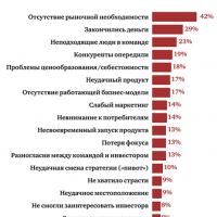 Five best business ideas that brought millions What business to open so as not to go bankrupt