The sequence of development of technological processes of mechanical processing. The main stages of the design of technological processes of machining The sequence of design of the technological process
9.1 Tasks in the design of technological processes
9.2 The order of development of technological processes of machining
Process design is an important element of the manufacturing process. The quality and cost of products depend on the degree of rationality of the technological process.
When designing technological processes, two main tasks must be solved:
– technological process for the given conditions and scale of production must ensure a reliable (without scrap) implementation of all the requirements of the working drawing and technical conditions on the product:
- the technological process should be as economical as possible (with minimal labor and means of production).
When designing technological processes, it is necessary to take into account modern directions in mechanical engineering technology. To select the most economical variant of the technological process, it is often necessary to draw up two or three competing variants, which are compared with each other. Usually, all other things being equal, preference is given to the most economical option.
The degree of elaboration of the technological process... Depending on the scale of production, the technological process is developed in more or less detail. In single and small-scale production, technological development is not developed in detail. In these conditions, the so-called route technology ("technological route") is made up - a list of operations, and for each operation the piece time and work category are determined. However, when processing complex and expensive parts, even in a one-off production, technological processes are developed in more detail.
In serial production, a route-operational description of the technological process is presented. The most complex operations include operational processes (with cutting modes), and simple ones - a technological route. For complex and critical parts (gearbox housings, crankshafts and others) develop an operating technology (typical for mass production).
With large-scale and mass production, an operating technology is made up, which is more detailed than a route-operating one.
The order of development of technological processes of mechanical processing. The design of technological processes consists of the following interrelated stages: analysis of initial data; technological control of the drawing of the part; selection of the type of production; selection of workpieces; choice of bases; establishing a route for processing individual surfaces of a part; designing a technological route for manufacturing a part with a choice of equipment type; calculation of allowances, calculation of intermediate and original dimensions of the workpiece; construction of operations and selection of technological equipment; calculation of processing modes; technical regulation of operations; evaluation of technical and economic indicators of the process, registration of technological documentation.
Analysis of initial data... The initial data for the design of the process of machining parts include: working drawings of parts and specifications for their manufacture; data on the annual production program; data on the blanks from which the parts are to be made; information on specific conditions of this production(operating, reconstructed, new plant). For a new plant, a technological process can be designed using the latest equipment. For an operating and reconstructed plant, you need to have information about the equipment available.
When designing technological processes, a number of reference and regulatory and technical materials are also required (for allowances and tolerances, for equipment - passports, catalogs, etc., for cutting, measuring and auxiliary tools, cutting modes, auxiliary time, regulatory safety documentation, forms technological documentation (route maps, technological maps and operational control cards).
Technological control of the drawing of the part... The design of machining technological processes begins with a careful study of the drawing and technical specifications for the finished part. In many cases, it is also required to familiarize yourself with the drawings of the assembly and the product, which includes the workpiece, with the working conditions of the part, the parts production program, as well as with the production conditions in which the process is planned to be performed (equipment, vehicles and etc.)
In the process of analyzing the initial data, the technologist carries out technological control of the drawing and technical conditions. In this case, it is necessary to identify ways to improve the manufacturability of the design of the part. This will reduce the labor intensity of manufacturing a part, reduce the cost of manufacturing it (standard tool, ratio of accuracy and roughness, etc.).
Selection of the type of production. The type of production is chosen based on production program release by calculating the timing of the release of parts. The size of the production program is determined based on the labor intensity of processing operations, the labor intensity of setting up equipment at the main operations, the cost of work in progress and other economic and organizational considerations.
Selecting the original stock... The choice of the workpiece and the method of its production is significantly influenced by the characteristics of the material from which the part should be made, its design forms and size, and the release program.
The method of obtaining the workpiece should ensure the lowest production cost of the workpiece.
Selection of technological bases is the basis for constructing a technological process for manufacturing a part and is of great importance for ensuring the required processing accuracy of the cost-effectiveness of the process. When assigning technological bases for the first and subsequent processing operations, one should be guided by the following general considerations:
- the installation and guide base must have the required length to ensure the stable position of the workpiece during its processing;
- the workpiece to be processed must have minimal deformations from the action of the cutting force, clamping force and from the action of its own mass;
- as a technological base, surfaces should be taken that provide the smallest installation error and exclude a basing error.
At the first operation, those surfaces must be processed that will be taken as a technological base for subsequent operations.
Since the technological base in the first operation will be rough (not processed) surfaces, you should choose those surfaces that allow as uniform removal of allowances as possible and a sufficiently accurate relative position of the surfaces to be processed and not to be processed. If all surfaces of the part are machined, then surfaces with the smallest allowance should be selected as a base in the first operation, so that during subsequent processing there will be no rejects due to a lack of allowance.
In the second and subsequent operations, the technological bases should be as accurate as possible in terms of geometric shape and surface roughness.
It is recommended, if possible, to observe the principle of overlapping bases, i.e. as a technological base, take surfaces that will simultaneously be a measuring base. If the technological base does not coincide with the measuring one, then a basing error occurs. It should be borne in mind that the best results in terms of accuracy will be achieved if the design base serves as the technological and measuring base.
It is necessary to adhere to the principle of the constancy of the base on the main processing operations, i.e. use the same surfaces as a technological base. In order to comply with the principle of constant bases, in a number of cases, artificial technological bases are created on the parts that do not have a constructive purpose (center seats of the shafts, specially machined holes in body parts when basing them on pins, etc.).
If, according to the processing conditions, it is not possible to maintain the principle of the constancy of the base, then the processed surface is taken as a new base, which is as accurate as possible and ensures the rigidity of the workpiece installation.
Establishing a route for processing individual surfaces of a part. At the initial stage of the development of the technological process, a list of technological transitions is drawn up that can be applied to achieve the final accuracy and surface roughness indicated on the working drawing of the part. There are close links between the working drawing and the manufacturing process of the part. They are due to the fact that each processing method corresponds to a certain achievable accuracy of the resulting size and surface roughness. Therefore, the required surface finishing method is suggested by the working drawing of the part.
The choice of finishing method is facilitated by using the precision characteristics of various technological methods. Since each method of processing corresponds to some optimal value of the stock, and the total stock usually exceeds the value allowed for this method, it is possible to determine the methods of previous processing. For example, when machining a shaft journal up to a diameter of 50h8 when using rolled stock as a workpiece, the sequence of technological transitions: 1) rough turning, 2) finishing turning, 3) grinding. In this case, the transition of rough turning is necessary to approximate the shape and dimensions of the workpiece to the shape and dimensions of the part.
Having determined the first and final transitions, they establish the need for intermediate transitions. For example, when machining a hole according to the 7th grade of accuracy, after the first transition (rough boring of a hole), it is unacceptable to immediately apply a finishing reaming, since the accuracy and surface quality after rough boring will not ensure a high-quality execution of a finishing reaming.
Determining the sequence of technological transitions in the processing of individual surfaces allows you to identify the necessary stages of processing (roughing, finishing and finishing) and is the basis for the formation of a technological route for the manufacture of parts and individual operations.
Designing a technological route for manufacturing a part with a choice of equipment type. At the stage of developing a technological route, allowances and processing modes are not calculated, therefore, a rational route is chosen using reference data and guidance materials on standard and group processing methods.
Technological routes are very diverse and depend on the configuration of the part, its dimensions, the required accuracy, the release program, however, when designing the route, some general considerations should be followed. From a methodological point of view, this work can be represented by the following exemplary scheme.
First, they identify the need to subdivide the part manufacturing process into roughing, finishing and finishing operations. This work is performed using developments to establish a processing route different surfaces this part.
It is advisable to separate the roughing operation from the finishing operation in order to reduce the effect of deformation of the workpiece after roughing. However, if the workpiece is rigid and the machined surfaces are insignificant in length, then such dismemberment is not necessary.
Finishing, as a rule, is carried out at the final stage of the process, but in some cases it is necessary to deviate from this position.
When forming operations, it should be taken into account that specific group surfaces will require processing from one installation. Such surfaces include coaxial surfaces of revolution and adjacent end surfaces, as well as flat surfaces processed in several positions.
In independent operations, the processing of wheel teeth, cutting of splines, processing of grooves, drilling of holes using multi-spindle heads, etc. are distinguished.
When shaping transactions, keep in mind the following:
- in the first operation, it is necessary to process those surfaces that will be used as installation bases in the second, and possibly in subsequent machining operations;
- the presence of thermal or chemical thermal treatment.
When forming a technological route the type of equipment used is established. The machine is chosen according to passports, catalogs, according to the actual availability in accordance with the nature of processing, the requirements for accuracy and surface roughness at a given operation, the size of the workpiece being processed, and the scale of production.
The dimensions of the machine must match the dimensions of the workpiece. It is necessary to strive for the most efficient use of the machine in terms of power and time, and for multi-position - positions and supports. When choosing a machine, an important factor is its cost and the cost of processing a part on it.
In single production they use universal machines, serial - specialized, and in the mass - special (automatic, semiautomatic, modular, etc.)
The completed outline of the technological route is drawn up in the form of operational sketches of blanks with an indication of the scheme of their basing and with the highlighting of the surfaces to be treated with bold lines.
The route of the technological process includes omitted minor operations (machining of fastening holes, chamfering, deburring, flushing, etc.).
Place of thermal operation in the technological route... In the process of manufacturing a part, heat treatment operations should be linked to machining operations. Distinguish between preliminary, intermediate and final heat treatment.
Preliminary maintenance is carried out before performing machining operations and consists in annealing, normalizing or improving the workpieces. Forgings made of structural materials, castings and welded blanks are subjected to annealing operations, which sharply reduce residual stresses in the material and improve its machinability by cutting. If, in the manufacture of parts from medium-carbon steels, the final heat treatment consists in normalization or improvement, then these operations are performed before machining. Improvement is carried out to a hardness not higher than HRC 40 (HB 390), since at a higher hardness, processing with a razor tool is difficult. Intermediate maintenance - is used after rough cutting and consists in normalizing steel parts and in the aging process of castings. Workpieces made of low-carbon steels, including those made of alloyed low-carbon steels (20X, 20XH), are subjected to normalization in order to ensure better machinability during finishing cutting or when processing by plastic deformation (hole rolling, etc.). Final maintenance is carried out in the form of general hardening of the part or surface hardening. If the final heat treatment consists in general hardening of the part to a hardness higher than HRC 40, then this treatment is carried out after finishing before grinding. If carburizing with subsequent hardening of individual surfaces of the part is necessary, preliminary copper plating of those surfaces that are not subject to carburizing is used. To protect the surfaces to be carburized from being coated with a layer of copper, dielectrics, most often varnish, are applied to these surfaces.
Determination of allowances... The total machining allowance is equal to the sum of the intermediate allowances. The total machining allowance depends on a number of factors: the size and configuration of the parts, the material of the part, the accuracy of the part, the method of manufacturing the workpiece, etc.
The allowances should be set as optimal for the specific processing conditions. Overestimated allowances lead to unnecessary material consumption, an increase in the labor intensity of machining, and an increase in the operating costs of machining (consumption of tools, electricity, etc.). Insufficient allowances can prevent correction of errors from previous machining and obtaining the required accuracy and roughness of the machined surface at the transition being performed.
The values of the allowances are established according to the experimental statistical data (standard tables) or by the calculation and analytical method.
The computational and analytical method for determining the allowances is applicable for mass, large-scale and medium-batch production. In the conditions of single and small-scale production, allowances are set according to standard tables.
Based on the calculation of intermediate allowances, it is possible to determine the limiting intermediate and original dimensions of the workpiece. Scheme construction begins with the smallest size limit after finishing. The largest limiting dimensions of blanks are obtained by adding technological tolerances to the smallest diametrical dimensions (for finishing turning, rough turning and tolerance for the size of the original blank).
The largest allowances are obtained by subtracting the largest limit dimensions of the workpiece at the previous and ongoing transitions.
Construction of operations and selection of technological equipment. When designing technological operation perform the following interrelated work: choose the structure of the construction of the machining operation; clarify the content of technological transitions in the operation; choose the model of the machine; choose technological equipment; the processing modes are calculated; calculate the rate of time; determine the category of work; justify the effectiveness of the operation.
The design of the operation is a multivariate task, therefore the assessment possible options produced on the basis of technical and economic calculations. When designing individual operations, they specify the technological route for manufacturing a part and make the necessary adjustments to it.
When designing the structure of a machining operation, it is necessary to strive to achieve the most economical option. An important factor affecting the cost of production is the productivity of the process, assessed by the labor intensity of a unit of production, i.e. piece time. The main components of which are the main and auxiliary time.
In this regard, when forming an operation in order to possibly overlap the elements of the main and auxiliary time, schemes for constructing operations are considered, which differ:
- the number of simultaneously installed blanks (single and multiple schemes);
- the number of tools involved in processing - single-tool and multi-tool processing;
- the order of using the tools - sequential, parallel, parallel-sequential processing. The choice of a specific scheme for constructing an operation largely depends on the production program and the size of the part. In the case of a single production of parts of any size, the most rational will be a single-site single-tool sequential processing, and in the case of serial and mass production of medium-sized parts, multi-site multi-tool parallel or parallel-sequential processing.
Figure 29 - Examples of single-site processing
Figure 29 shows examples of single-tool processing: a - single-tool sequential turning of a stepped shaft: b - sequential processing with several tools - drilling and countersinking a hole; c - parallel multi-tool machining - drilling and simultaneously external turning; d - parallel-sequential processing - performing milling-centering operation in two positions: in the 1st position - simultaneous milling of two ends, in the 2nd position - simultaneous centering of the ends.
Selection of technological equipment... Simultaneously with the choice of equipment, a device, a cutting and measuring tool is selected. When choosing technological equipment, one should take into account the type of production, the type of product and its production program, the nature of the planned technology, the possibility of maximum use of the existing standard equipment.
The choice of fixtures depends to a large extent on the part program:
- in single and small-scale production, devices are used universal type(vice, cam chucks, dividing heads, etc.);
- serial - universal readjustable devices and devices for group processing;
In the mass - high-performance special devices that allow to drastically reduce the time for setting and fixing the workpiece before processing and for removing the workpiece at the end of the operation.
Choosing a cutting tool produced with a couple of the processing method, the material of the workpiece, its size and configuration, the required quality of the processed surface, the program for the release of parts. When choosing a cutting tool, first of all, they are guided by the use of a standard tool, however, in certain operations, especially in conditions of serial and mass production, a special tool is provided. For the cutting part of the tool, hard alloys are widely used, which provide high speeds cutting and super hard. Hard alloys: mono-carbide (VC) - for processing cast irons and non-ferrous alloys; two-carbide (TC) - for processing viscous materials; three-carbide (TTK) - for high-speed cutting, finishing. In finishing processing, the use of diamonds (natural and synthetic) is expanding, especially when processing non-ferrous metals and alloys (bronze, brass, aluminum alloys, etc.), for dressing grinding wheels.
The choice of measuring instruments is made taking into account the compliance of the accuracy characteristics of the tool with the accuracy of the size being performed, the type of surface being measured, and the scale of the release of parts. In the conditions of single and small-scale production, mainly universal tools are used: calipers, micrometers, bore gauges, universal indicator instruments, etc. With an increase in the scale of production of parts, the use of limit calibers, templates, various control devices and automatic controls increases.
Calculation of processing modes. The machining modes are characterized by depth of cut, feed and cutting speed. First of all, the depth of cut is prescribed, then the feed and, last of all, the cutting speed. The methodology for calculating cutting conditions for single-tool processing is as follows.
First of all, the limiting dimensions are determined:
- calculated diameter for outer surfaces - D p = D pre-operative and for inner surfaces - D p = D last opera; when milling, drilling and a fixed part, the calculated diameter is the outer diameter of the tool;
- the estimated length of processing, taking into account the infeed and overrun of the tool and the taking of trial chips - L = l 1 + l + l 2 + l pr.
The depth of cut during roughing is assigned based on the considerations of removing the allowance in one working stroke; in this case, the depth of cut will correspond to the intermediate allowance.
Estimated machining allowance
- external surfaces -;
- internal surfaces -.
If the allowance exceeds the allowable for a given case of processing, then assign two or more working strokes i = 1; 2…, but the maximum allowable depth of cut is taken in order to reduce the number of working strokes. When finishing, the depth of cut is assigned based on the condition of ensuring the accuracy of the resulting size and the specified surface roughness. Cutting depth.
After setting the depth of cut, the feed is selected. The feed is influenced by the depth of cut, the nature of processing, the material to be processed, the section of the tool holder (for turning). An interval is usually given, for example ![]() mm / rev. The feed should be as technologically acceptable as possible. During roughing, the feed is limited by the strength and rigidity of the elements of the technological system, they try to choose the highest feed and take its closest value for the machine mm / rev. When finishing, the feed is selected depending on the specified surface roughness, taking into account the workpiece material, cutting speed and radius at the tip of the tool (for turning). A smaller feed is chosen and corrected according to the passport data of the machine.
mm / rev. The feed should be as technologically acceptable as possible. During roughing, the feed is limited by the strength and rigidity of the elements of the technological system, they try to choose the highest feed and take its closest value for the machine mm / rev. When finishing, the feed is selected depending on the specified surface roughness, taking into account the workpiece material, cutting speed and radius at the tip of the tool (for turning). A smaller feed is chosen and corrected according to the passport data of the machine.
The service life of the cutting tool T is selected according to the standards (average value) depending on the size and type of the cutting tool, the characteristics of the material of the workpiece and working conditions.
After determining the feed depth and the tool life period, the cutting speed is determined:
![]() ,
,
where T m is the tool life period;
C V is a constant depending on the material of the tool, the material of the part, the type of processing and the nature of the processing;
t is the depth of cut;
s - feed;
m, x v, y v - exponents, determined from the reference book.
The cutting speed depends on the selected depth of cut and feed, the quality of the work material, the cutting properties of the tool, the geometric parameters of the cutting element of the tool, and other factors. In everyday practice, the cutting speed is determined on the basis of the standards of the modes and amendments are made in connection with factors not taken into account by the standards, m / min.
According to the cutting speed, the calculated rotational speed of the cutting tool or workpiece (n) or the calculated number of double strokes of the tool per minute is found.
K p - correction factor, is a product of a number of factors that take into account changes in cutting conditions
K p = K M K φ K γ K λ K r.
The effective power on the cutter is determined by the formula N e = P z · V · 10 -3, kW. The power on the drive of the machine is determined by the formula N pr = N e / η st and is compared with the power of the machine (N pr must be less than N e).
Based on the found values of the cutting mode, a verification calculation is made according to the feed force allowed by the strength of the machine tool feed mechanism, by the torque allowed by the strength of the main drive, according to the machine power. If necessary, correct the calculated values of feed and cutting speed.
PROCESS DESIGN SEQUENCE
CLASSIFICATION OF TECHNOLOGIES
INDUSTRIAL TECHNOLOGIES AND TECHNICAL PROGRESS
INTRODUCTION
INDUSTRIAL TECHNOLOGIES AND INNOVATIONS
Today's biggest challenges National economy Russia are: improving the quality characteristics of manufactured industrial products, reducing its cost and increasing labor productivity, significantly expanding the scale of technical re-equipment of existing enterprises, equipping them with new highly efficient equipment, the introduction of progressive technology and modern management methods.
Reducing material consumption, increasing the efficiency of use material resources, the use of advanced materials is one of the most pressing problems of industrial production. The creation and development of new materials with high performance characteristics and stability of physical and mechanical properties over time will allow the development of fundamentally new samples of consumer goods and high demand, which determine the economic situation of the relevant industry and the country as a whole.
The introduction of high-performance and precision equipment, qualitatively new technological processes based on an innovative principle is the main way to increase the industrial capacity of modern production. Such equipment and processes should be widely used in the manufacture of high technology products that meet the best world standards and are in high demand on the world market.
There are plenty of concepts and forecasts concerning the future of Russia in the 21st century. The approaches and opinions in them sound very different. Some of the Western countries adhere to the point of view expressed in one of his speeches by former British Prime Minister John Major. Speaking about the future of Russia, he predicted its role as a storehouse of resources for the needs of the West, adding that 40-50 million people will be enough for this. If we accept the logic of such a forecast, then the financial elite generated by transnational corporations, which rules the world, has actually already made a choice for Russia - a “stoker” and a “hallway”. But then this very elite will have to ascribe a number of rather paradoxical qualities - shortsightedness, imprudence, a tendency to generate hotbeds of tension. While provoking instability, biting the pride of the still nuclear power, the global financial elite, if any, looks too desperate and insidious.
An alternative scenario is based on the so-called economic growth strategy. It is based on a stake on enhancing the competitive advantages of the Russian economy. There are eight of them:
1. The level of education together with an orientation towards collectivism;
3. Territory and capacious domestic market;
4. Cheap and qualified enough work force;
5. Scientific and industrial potential;
6. Science schools and competitive technologies;
7. Free production capacity,
8. Experience in exporting high-tech products and industrial cooperation.
To realize all these advantages, of course, a system of economic and administrative measures must be thought out. Calculations already in the medium term promise sustainable economic growth of at least 7% per year, an overall increase in investment by at least 15% per year, and in high-tech industry and new technologies - up to 30%. Inflation will also be capped at 30% per annum ...
Many specialists place their main hopes on the realization of the country's scientific and industrial potential. Russia, which has 12% of the world's scientists, actually has no other serious alternative. For raw materials, even with 28% of the world's reserves, it is impossible to achieve an acceptable economic recovery. According to forecasts, its consumption will only double by 2015 by 2015, and we are already lagging behind developed countries by about 10 times in terms of gross domestic product per capita (GDP). But the volume of the world market for high technology products today is 2 trillion. 500 billion dollars (Russia's share is 0.3%). By 2015, it will reach about $ 4 trillion. dollars. Even a tenth of this amount is about an order of magnitude higher than the potential Russian oil and gas exports. On the other hand, the chances of promoting the innovation process on a national scale, letting inflation go up to 30% a year, seem problematic. It is known from world experience (Argentina) that this is the maximum level, above which inflation becomes the main obstacle to economic growth.
By all key indicators, the country has the same industrial infrastructure as Western countries. And only in the development of the technological environment (quality assurance systems, standards, automation of development, computerization of production, etc.) we are very far behind them. The level of development of technological infrastructure is ϶ᴛᴏ and there is a kind of watershed between industrial and post-industrial countries. This is what Russia must overcome.
How seriously are we lagging behind in this regard? The numbers speak for themselves. In 2008 ᴦ. each person employed in the Russian economy contributed $ 16.1 thousand to the country's GDP. Let's compare: in South Africa this figure was 38.1 thousand, in France - 59.4 thousand, in the USA - 74.6 thousand, in Luxembourg - 110 thousand. Why is this happening? Where does this difference come from? On the one hand, enterprises in developed countries produce higher quality and more sophisticated products than in Russia. It sells for more and has much higher added value. On the other hand, the much more advanced technical equipment of Western enterprises ensures greater labor efficiency and allows the production of a larger amount of finished products.
For example, let's take two automobile companies that employ an equal number of employees: AvtoVAZ - 106 thousand people and BMW - 107 thousand. AvtoVAZ produces an average of 734 thousand cars a year with a total value of $ 6.1 billion, BMW - 1.54 million cars. by 78.9 billion. That is, in "natural" terms, the productivity at AvtoVAZ is 2 times less, and in value terms - more than 13 times.
The analysis of the world market shows: the production of high technology products is provided by only about 50 macro technologies (macro technology is a combination of knowledge and production capabilities for the release of specific products on the world market - aircraft, reactors, ships, materials, computer programs etc.). The seven most developed countries, possessing 46 macro technologies, hold 80% of this market. The USA annually receives about 700 billion dollars from the export of science-intensive products, Germany - 530, Japan - 400. Forecast for 16 macro technologies has already been made (see table).
Macro technology market (in billions of dollars)
2010 ᴦ. 2015 ᴦ.
Aviation technologies 18-22 28
Space technologies 4 8
Nuclear technology 6 10
Shipbuilding 4 10
Automotive 2 6-8
Transport engineering 4 8-12
Chemical engineering 3 8-10
Special metallurgy. Special chemistry.
New materials 12 14-18
Oil production and processing technology 8 14-22
Gas production and transportation technology 7 21-28
Power engineering 4 12-14
Industrial technology
equipment. Machine-tool building 3 8-10
Micro- and radioelectronic technologies 4 7-9
Computer and information
technology 4.6 7.8
Communication 3.8 12
Biotechnology 6 10
Total 94-98 144-180
The world market is fiercely competitive. So, over the past 7-10 years, the United States has lost 8 macro technologies and, accordingly, their markets. As a result, we got a deficit in effective demand of $ 200 billion. The reason for this is that about 15 years ago, the Europeans formed a common program with the aim of winning a share of the market from the United States and Japan. Technologies were rebuilt for it, fundamental research was carried out, and industry was restructured.
A similar targeted attack is now being undertaken by a European aviation consortium. Its experts identified the possibility of winning 25% of the heavy aircraft market ($ 300 billion). A corresponding international program was formed. Even American competitors were drawn into it by buying up their firms. Russia was offered to create a joint research center, signed contracts with our factories. In general, 20% of the total volume of the program became Russian. In a word, the history of this major transnational project clearly testifies: in the distribution of orders, business expediency turns out to be decisive, above all.
According to our experts, for the market of 10-15 macro technologies out of those 50 that determine the potential of developed countries, Russia is quite capable of competing. The choice of macrotechnological priorities in our country should be carried out on a principle that is completely new for us. Supporting dozens of priority scientific and technical programs on the entire front of conceivable research is completely unpromising. Even the richest country cannot afford this today. In order to assign a particular macrotechnology the priority status for our country, it is proposed to compare the costs of forming a knowledge base on it (complete or sufficient) and the possible effect of the sale of competitive products created on its basis.
Federal target programs are formed for each priority macrotechnology. The government places orders for them on a competitive basis with institutes and design bureaus. As a result, the industry receives a related set of tasks for the design of integral technological systems. (By the way, according to a similar scheme, Russia, having adopted the target program "Fighter-90s" 15 years ago, conquered the market with a volume of $ 5 billion, a similar analogy arises if we recall the program for the creation of rocket and space technology). A competitive technological environment harmonized with world standards is being created. And since all targeted programs are deliberately focused on world-class end products, their attractiveness for Western and Russian investors and creditors will be quite high. The role of the state is to guarantee risk loans.
For Russia now, more than ever, integration into the world market of science-intensive technology is urgent. There is almost no effective demand for a part of science-intensive products in the country, which leads to stagnation and aging of the most advanced technological base (aviation, astronautics, electronics, computer science, communications, etc.). According to forecasts, the volume of exports for priority macrotechnologies already in the first twenty years of the 21st century will allow to increase the population's solvency by 2-3 times and ensure the demand for high-tech products in the domestic market. This will stimulate further economic growth.
The concept of national macro-technological priorities was met with interest not only among specialists, but also in the government. This allows us to hope that in the 21st century we are still able to make a worthy choice ourselves - not in favor of the “stoker” and the “hallway”.
In modern technical (and not only) literature, various variants of the concept of "technology" are widely used. It is advisable to somehow systematize these definitions.
Technology(Technology) - literally translated, the science of craftsmanship.
There are a number of domestic definitions, of which we will cite only encyclopedic ones:
1. Science or a set of information about the methods of processing raw materials, materials, semi-finished products, components, and now software into products that meet the specified requirements in terms of their technical purpose and quality.
2. The totality of means, processes, operations, methods by which elements entering into production are transformed into outgoing ones; it covers machines, mechanisms, skills and knowledge.
Foreign (Western) definition: application (use) of something in industry, commerce, medicine and other areas.
Progressive technology... A technology of a higher stage of development (in comparison with the existing one), which is the result of the introduction of process innovations. This category includes technologies based on borrowed best practices when new or improved methods of manufacturing products are introduced, incl. previously implemented in industrial practice in related areas of one enterprise, other enterprises and other countries and distributed through technological exchange (non-patent licenses, know-how, engineering, etc.).
Science-intensive technology... Technology based on new or significantly improved production methods. New technology corresponds to the concept of radical product innovation, and improved - to incremental product innovation.
Science-intensive technologies - ϶ᴛᴏ technologies focused on the production of products, performance of work and services using the latest achievements of science and technology, when the resulting product corresponds in its economic and operational properties to the best world standards and fully satisfies the new needs of society in comparison with the previously produced similar purpose ... The creation of such technologies includes the provision of scientific research and development, which leads to additional costs of funds and the utmost importance of attracting scientific potential and personnel to the work. Science intensity is an indicator reflecting the proportion between scientific and technical activities and production in the form of the amount of costs for science per unit of production. It can be represented by the ratio of the number of people employed in scientific activities and all those employed in production (at an enterprise, in an industry, etc.).
High technology(High Technology). A technology based on the creation of new properties of products by influencing materials on the intermolecular, interatomic, intraatomic, etc. levels. Examples of such effects can be the use of nuclear radiation energy (polymerization of high molecular weight compounds), cosmic radiation (obtaining ultrapure materials), laser, plasma, ultrasonic, etc. types of processing.
Critical technology... Technology, the development of which is due to a critical situation caused by the extreme importance of urgent production in conditions of limited time and limited material resources. A technology that is far from optimal, when the main thing is not the cost of products, but the extreme importance of their manufacture by a certain calendar date.
The development of technological processes (TP) is included in the main section of the stage " life cycle products "associated with the technological preparation of production, and is carried out on the basis of the principles" Unified system technological preparation of production "(GOST 14.001-83). TP can be developed using the existing standard or group TP. In the absence of such TP is developed as a single, taking into account previously adopted progressive solutions in existing single TP - analogs.
The basic initial information for the design of TP are: working drawings of the product in electronic form or in hard copy, technical requirements, the volume of the annual production of products, the availability of equipment and tooling.
In mechanical engineering, a product is a production item to be manufactured. A product can be a machine, device, mechanism, tool, etc. As component parts assembly unit and part are accepted. Assembly unit - ϶ᴛᴏ part of the product, the constituent elements of which are to be connected at the enterprise, separate from other elements of the product. An assembly unit, depending on the design, can either consist of separate parts or include assembly units of higher orders and parts. There are assembly units of the first, second and higher orders. An assembly unit of the first order is included directly into the product. It consists of either individual parts or one or more assembly units second order and details. An assembly unit of the second order is dismembered into parts or assembly units of the third order and parts, etc. An assembly unit of the highest order is exploded only into parts. The considered division of the product into its component parts is made according to the technological basis.
Part - ϶ᴛᴏ a product made of a material of the same name and brand without the use of assembly operations. A characteristic feature of a part is the absence of detachable and one-piece connections in it. A part is a complex of interconnected surfaces that perform various functions during machine operation.
The production process - ϶ᴛᴏ the totality of all actions of people and tools required for this enterprise for the manufacture and repair of products. For example, the production process of making a machine includes not only the manufacture of parts and their assembly, but also the extraction of ore, its transportation, transformation into metal, and obtaining blanks from metal. In mechanical engineering, the production process is part of the overall production process and consists of three stages: obtaining a blank, converting the blank into a part, and assembling the product. Given the dependence on specific conditions, the three stages listed can be carried out at different enterprises, in different shops of the same enterprise, and even in the same shop.
Technological process is a part of the production process that contains purposeful actions to change and (or) determine the state of the object of labor. By a change in the state of the object of labor, it is customary to understand a change in its physical, chemical, mechanical properties, geometry, appearance... At the same time, the technological process includes additional actions directly related to or accompanying a qualitative change in the production object; these include quality control, transportation, etc. For the implementation of the technological process, a set of production tools, called technological equipment, and a workplace are required.
Technological equipment - ϶ᴛᴏ means of technological equipment, in which materials or workpieces, means of influencing them, as well as technological equipment are placed to perform a certain part of the technological process. These include, for example, foundry machines, presses, machine tools, testing stands, etc.
Technological equipment - ϶ᴛᴏ means of technological equipment, supplementing technological equipment for performing a certain part of the technological process. These include: cutting tools, fixtures, measuring instruments.
Technological equipment together with technological equipment, and in some cases a manipulator, is usually called a technological system. This concept emphasizes that the result of the technological process depends not only on the equipment, but also, to no less extent, on the device, the workpiece tool.
It is customary to call a workpiece an object of labor, from which a part is made by changing the shape, size, surface properties or material. The workpiece before the first technological operation is called the original workpiece.
Workplace is an elementary unit of the structure of the enterprise, where the performers and the serviced technological equipment, lifting and transport vehicles, technological equipment and objects of labor are located.
For organizational, technological and economic reasons, the technological process is divided into parts, which are usually called operations.
It is customary to call a technological operation a part of a technological process performed at one workplace. An operation encompasses all the actions of equipment and workers on one or more production facilities. When machining on machines, the operation includes all the actions of the worker who controls the technological system, the installation and removal of the object of labor, as well as the movement of the working bodies of the technological system. The number of operations in the technological process can vary from one (manufacture of a part on a bar machine, manufacture of a body part on a multi-operation machine) to many tens (manufacture of turbine blades, complex body parts). The operation is formed mainly according to the organizational principle, since it is the main element production planning and accounting.
In turn, the technological operation also consists of a number of elements: technological and auxiliary transitions, installation, positions, working stroke.
Technological transition is a complete part of a technological operation performed with the same means of technological equipment under constant technical conditions and installation. Auxiliary transition - ϶ᴛᴏ a finished part of a technological operation, consisting of human actions and (or) equipment, which are not accompanied by a change in the properties of the object of labor, but are necessary to perform a technological transition (for example, installing a workpiece, changing a tool, etc.). The transition can be performed in one or more work passes.
Working stroke - ϶ᴛᴏ the finished part of the technological transition, consisting of a single movement of the tool relative to the workpiece, accompanied by a change in the shape, dimensions, surface quality and properties of the workpiece. When machining a workpiece with material removal, the term "stock" is used.
An allowance is usually called a layer of material removed from the surface of the workpiece in order to achieve the desired properties of the surface to be produced. The layer of material removed from one surface of the finished part as a result of performing all technological transitions is usually called the total allowance for processing this surface.
The stage of the product life cycle (LLC), associated with the technological preparation of production, provides for:
Designing a rational workpiece;
Development of route technology for the manufacture and assembly of products with the selection or design of initial blanks and extremely important technological equipment;
Development of operational technology for the manufacture and assembly of products with the selection or design of technological equipment (STO);
Development of technological documentation in accordance with the ESTD;
Generation of UE for equipment with CNC;
Selection or design of means of mechanization and / or automation of technological processes (TP);
Development of planning solutions for the placement of technological equipment in the envisaged area;
Keeping an archive of technological documentation;
Registration of changes in technological documentation related to design modifications or improvement of TP.
The workpiece is selected or designed based on considerations of optimizing the entire technological process (TP), including the blank stage and subsequent processing. When extremely important, a feasibility study is carried out. The workpiece is designed by the technologist mechanical workshop, and its production is carried out according to the technology of the procurement unit of the enterprise or a subcontractor.
When designing a workpiece, its dimensions are determined by the results of the calculation of the so-called. interoperative allowances. Allowance - a layer of material removed from the surface of the workpiece in order to achieve the specified properties of the machined surface of the part. Distinguish between the total allowance and intermediate allowances for all sequentially performed technological transitions and processing operations on a given surface of the part. The total allowance for any surface is the sum of the intermediate allowances for the same surface. Intermediate allowances are needed to determine intermediate (for technological transitions and operations) sizes of parts, general - to determine the size of workpieces. In practice, computational-analytical and experimental-statistical methods for calculating allowances are used.
Technology in any area of human activity - ϶ᴛᴏ a branch of science that studies the patterns of technological processes of manufacturing products, in order to use the results of the study to ensure the required quality and quantity of products with the highest technical and economic indicators. The science of technology is not just a sum of some knowledge about technological processes, but a system of strictly formulated statements about phenomena and their deep connections, expressed through special concepts. On the other hand, the science of technology, like any branch of knowledge, is the result of human practice; it is subordinated to the goals of developing social practice and is capable of serving as a theoretical basis.
The object of technology is the technological process, and the subject is the establishment and study of external and internal connections, the laws of the technological process. Only on the basis of their in-depth study is it possible to build progressive technological processes based on an innovative principle, ensuring the manufacture of high quality products at low cost.
Modern technology develops in the following main directions: creation of new materials; development of new technological principles, methods, processes, equipment; mechanization and automation of technological processes, eliminating the direct participation of humans in them. If the implementation of the technological process gives rise to the extreme importance of making tools of labor, being the reason for their appearance, then the development and improvement of tools of labor, in turn, stimulates the improvement of the process itself. The formation of technology as a scientific discipline is hampered by a huge variety of production facilities (from miniature devices to nuclear power plants, from the simplest products such as a hammer to the most complex machines such as a spacecraft), countless manufacturing methods and equipment for their implementation. This is due to a large number of classifications of technologies according to various criteria. Here are just a few.
Technological processes in terms of their functional composition are subdivided into blanking processes for obtaining blanks, processing blanks for obtaining parts and assembly processes.
For high-quality functioning procurement production very important modern approach to the design of the workpiece from the point of view of optimizing the cost of its production, taking into account the volume of subsequent processing and the utilization rate of the material. It is also necessary to take into account the volumes of production, because the approach to the construction of the technological process depends on this to a significant extent. Reducing the consumption of metals and other structural materials is achieved through their more efficient use, the use of progressive solutions in the design of new products, as well as the improvement of materials processing methods.
A significant reduction in material consumption can be achieved by switching to fundamentally new technological processes for the manufacture of blanks, the dimensions of which are as close as possible to the dimensions of finished parts. A reduction in machining allowances, in turn, is associated with an increase in the accuracy of workpieces and a decrease in the thickness of the defective surface layer. Low-waste production technology also contributes to the intensification of machining, since in some cases roughing operations (turning, gear hobbing and others) are excluded, which are successfully replaced by power grinding or other finishing with high cutting conditions.
As the configuration of the workpiece becomes more complex, the allowances decrease, the accuracy of dimensions and parameters of the location of surfaces increases, the technological equipment of the blank shop becomes more complicated and more expensive and the cost of the workpiece increases, but at the same time the labor intensity and cost of subsequent machining of the workpiece decreases, and the utilization rate of the material increases. Blanks of simple configuration are cheaper, since they do not require complex and expensive technological equipment in the manufacture, however, such blanks require subsequent laborious processing and increased material consumption.
The main thing when choosing a blank is to ensure the desired quality of the finished part at its minimum cost. The cost of a part is determined by summing up the cost of the blank according to the calculation of the blank shop and the cost of its subsequent processing until the specified quality requirements are achieved according to the drawing. The choice of the blank is associated with a specific technical and economic calculation of the cost of the finished part, carried out for a given volume of annual output, taking into account other production conditions.
The basic technological processes of low-waste production of blanks, as is known from the course "Technology of structural materials" include: progressive methods of manufacturing cast blanks from metals and plastics; methods of obtaining blanks by hot and cold plastic deformation, including the processes of making blanks without using pressing equipment (explosion, electric pulse), cold heading and calibration to exclude subsequent machining, etc .; methods of working with any sheet materials (metals, fabrics, leather, plastics, etc.) by cutting or cutting using advanced methods (flame, plasma, laser); modern methods and equipment for cutting materials, including electrocontact, which can significantly increase productivity when working with difficult-to-cut materials. Methods and equipment of powder metallurgy have become widespread for workpieces made of metal and mineral ceramics.
The basis of technological processes for the manufacture of parts is formed by shaping methods, methods of changing the physical and mechanical properties of a material, methods of influencing the quality of the surface layer (methods of coating, finishing, painting, etc.). Shaping methods, in turn, are divided into methods with material removal and without material removal. The former are subdivided into cutting methods (turning, planing, drilling, countersinking, reaming, milling, broaching, etc.), abrasive processing methods (grinding, honing, polishing, etc.), electrophysical and electrochemical methods.
Methods without material removal include methods of plastic deformation; methods of changing the physical and mechanical properties of a material include various types of heat treatment, chemical and thermal processes.
The assembly technological process contains actions for the installation and formation of connections of parts, assembly units into a product. This takes into account the technically and economically feasible sequence of obtaining the product. The quality of an assembly unit is characterized by the accuracy of the relative movement or arrangement of parts in the assembly unit, force-locking, interference in fixed joints, clearance in movable joints, quality of surface adhesion, and others.
An assembly operation is usually understood as the process of direct formation of an assembly unit. It usually includes orientation, connection, adjustment and fastening (fixation) of parts and assembly units. The assembly of connections can be conditionally divided into an assembly with an interference fit and without an interference fit. Interference assembly is carried out either by plastic deformation or by heat. In turn, the thermal method is implemented by heating the female part and (or) cooling the male part.
In terms of the scale of production, modern industrial production and, in particular, mechanical engineering, is conditionally divided into three types: single, serial and mass. The formation of operations for these types of industries is carried out in different ways, depending on the nature, type and form of organization of the assembly process.
One-off production is characterized by a small volume of production of identical products, the re-production and repair of which, as a rule, is not provided. Products are produced in a wide range of relatively small quantities, often individually, and either do not repeat at all, or are repeated at indefinite intervals. One-to-one production - products that are not widely used and manufactured according to individual orders, providing for the implementation of special requirements(prototypes of machines in various branches of mechanical engineering, large hydraulic turbines, unique metal cutting machines, rolling mills, etc.).
In the conditions of single and small-scale production, division into operations is carried out, as a rule, according to assembled assembly units on the basis that each machine consists of a number of assembly units: assemblies, sub-assemblies, kits and individual parts. This division of mechanical engineering products into assembly units is extremely important for ease of assembly and allows you to create machines on an aggregate basis. The unification of assembly units is of great importance, since it reduces the number of special assembly units and thus helps to reduce costs. Division into separate assembly units allows their manufacture and regulation simultaneously, independently of one another, and, consequently, reduce the time of machine production. In this case, it is desirable that each assembly unit would contain as few parts as possible.
Serial production is characterized by the manufacture or repair of products in periodic batches. Batch production is divided into small batch, medium batch and large batch. One of the indicators of belonging of a production to a certain type is the so-called. the coefficient of assignment of operations to one workplace. For small-scale production, the coefficient ranges from 20 to 10, for medium-volume production, respectively, from 20 to 10, for large-scale production - from 1 to 10.
Mass production characterized by a small nomenclature, a large production volume, continuous production or repair of products for a long time, during which one constantly repeating operation is performed at most workplaces. In the conditions of mass and large-scale production, the formation of transitions in the operation is carried out in accordance with the extremely important sequence of installation and fastening of parts and other assembly units to the assembled object so that the total time spent on the operation is close to or multiples of the production cycle. If it is possible to change the sequence of installation and fixing of assembly units, the transitions to operations are formed in such a way that one worker performs the same work and qualifications. This allows you to increase productivity, as the skills of the worker are improved, and to reduce the need for equipment and work tools.
In mass and large-scale production, special and specialized equipment is used, the changeover of which to a new (not known at the time of equipment design) type of product is impossible or is associated with significant costs. In medium- and small-scale production, the main share of the equipment park is still accounted for by hand-operated machine tools, the reserves of increasing productivity of which are basically exhausted. For this reason, an increase in the volume of this type of production requires a proportional increase in the number of skilled workers, the shortage of which is acutely felt even with the existing production volumes. As a result, the industry has faced two opposing challenges: ensuring the flexibility of large-scale production.
Answers.
Initial information and sequence of design of technological processes.
Technological processes are developed during the design of new, reconstruction of existing enterprises, as well as when organizing the production of new products at existing enterprises. At the same time, the adopted options are the basis for all technical and economic calculations and design decisions. The level of development of technological processes determines the level of the enterprise. In addition, technological processes are developed and adjusted in the conditions of operating enterprises in the production of mastered products. This is caused by continuous design improvements of products, the need for systematic use and implementation of the achievements of science and technology in existing production through the development and implementation of organizational and technical measures, the need to eliminate bottlenecks in production.
Initial data for the design of technological processes
Initial data (information) for the design of technological processes are subdivided into: basic; guiding; reference. Basic information includes the data contained in the design documentation for the product and the release program: a drawing of a part with technical requirements for manufacturing; assembly unit drawings defining service appointment parts and their separate surfaces; working conditions of parts; volume of issue; planned release dates. The governing information predetermines the subordination of decisions made to standards, taking into account promising developments. The guideline information includes: standards that establish requirements for technological processes and methods of managing them; equipment and tooling standards; documentation for operating single, standard and group technological processes, classifiers of technical and economic information; production instructions, materials for the selection of technological standards (processing modes, allowances, material consumption rates, etc.); labor protection documentation. TO reference information includes: experience in the manufacture of similar products, methodological materials and standards, results of scientific research Reference information includes: data contained in the technological documentation of pilot production; description of progressive manufacturing and repair methods; catalogs, passports, reference books; albums of layouts of progressive means of technological equipment, layouts of production sites; methodological materials for the control of technological processes.Extensive reference information is also contained in textbooks, teaching aids, guidelines, monographs and periodicals... When designing technological processes for operating enterprises, the general production environment should be taken into account: availability of areas; composition and degree of equipment loading; availability of technological equipment; provision of the enterprise with qualified labor force, etc.
The sequence of designing technological processes for the manufacture of machine parts.
The process of technological design contains a number of interrelated and performed in a certain sequence of stages. These include: analysis of the initial data; technological control of the drawing; determination of the type and organizational form of production; selection of the type of the original workpiece and the method of obtaining it; selection of the type of technological process; development of the technological code of the part based on the technological classifier; selection of technological bases and workpiece basing schemes; the choice of methods for processing the surfaces of the workpiece; designing a processing route; development of the structure of operations; selection of technological equipment (equipment, accessories, cutting and measuring tools); designation and calculation of processing modes, designation and calculation of allowances and operating dimensions: standardization of the technological process and determination of work qualifications; selection of means of mechanization and automation of elements of the technological process and means of in-shop transport; planning (if necessary) and development of operations for moving parts and waste; development of measures to ensure safety requirements and industrial sanitation; comprehensive technical and economic assessment of the technological process; registration of technological documentation.
Design of standard and group technological processes.
Typical TP is a technological process of manufacturing a group of products with common design and technological features.
Group TP is a technological process of manufacturing a group of products with different design, but common technological features.
Technology of manufacturing bodies of revolution.
Shafts include parts formed by the outer and inner surfaces of revolution; having one common rectilinear axis with the ratio of the length of the cylindrical part to the largest outer diameter of more than two. Shafts are classified according to various criteria: By the shape of the outer surfaces: stepless; stepped; with fittings (cones, splines, flanges, toothed rims, cams, slats, etc.). By the shape of the inner surfaces: solid; hollow. By size ratio: hard: non-rigid. Shafts are considered rigid if the ratio of length to diameter does not exceed 10 ... 12. Shafts with a large ratio are called non-rigid. A special group is made up of crankshafts, cam shafts, spindles and large shafts (more than 200 mm in diameter and weighing more than 1 ton).
The main technological tasks when processing shafts are as follows: maintain the accuracy and roughness of surfaces, maintain the straightness of the common axis; maintain concentricity of surfaces of rotation; maintain alignment of threads with outer surfaces or precise inner cylindrical holes; ensure parallelism of keyways and splines of the shaft axis.
Basic basing schemes
The main design bases of most shafts are the surfaces of the bearing journals. However, it is difficult to use them as technological bases for processing external surfaces at all operations. For the condition of maintaining the unity and constancy of the bases, the surfaces of the center holes are taken as technological bases. To eliminate the positioning error when maintaining the lengths of the steps from the end of the shaft, it is necessary to use the end of the workpiece as a supporting technological base. For this purpose, the workpiece is placed on a floating front center. The transmission of torque when the shaft is installed in the centers is carried out using a drive chuck or a clamp.
Bushing manufacturing technology
Bushings include parts formed by the outer and inner surfaces of revolution having one common rectilinear axis with the ratio of the length of the cylindrical part to the largest outer diameter of more than 0.5 and less than or equal to 2.
Technological tasks when processing bushings, they consist in achieving concentricity of the outer and inner surfaces and perpendicularity of the ends to the axis of the hole. When making thin-bone bushings, an additional task arises of securing the workpiece and processing it without deformations.
Basic basing schemes
Technological routes for processing bushings, depending on their accuracy and configuration, are built according to one of three options: 1 Processing of external surfaces, holes and ends in one setup. It is used for the manufacture of small bushings, not thermally processed, from a bar or pipe on automatic turret lathes, single-spindle or multi-spindle automatic lathes. Technological base- the outer surface and the end of the bar. 2 Machining of all surfaces in two sets or in two operations with basing when finishing the outer surface along the hole (machining from the center to the periphery). It is used in cases where the accuracy of the inner hole is specified by the drawing higher than the outer surface. In this case, the order of roughing passes is not strictly regulated. During finishing, the hole is machined first. The machined hole is taken as the technological base (using a mandrel) and the outer surface is finally machined. 3. Processing of all surfaces in two sets or in two operations with basing when finishing on the outer surface (processing from the periphery to the center ) It is used in cases where the accuracy of the outer surfaces according to the drawing is higher than that of the inner hole. Any order of rough transitions. When finishing, the outer surface is machined first. This surface is taken as the technological base (in the chuck) and the inner hole is machined. When choosing a locating scheme, preference should be given to locating along the hole (machining from the center to the periphery).
Painting (for casting).
Turning: Rebore the hole with a post-machining allowance and trim the butt end.
Technological base- black surface of the rim or hub and end face Performed depending on the design and type of production on a lathe, revolving or carousel lathe.
Turning. Trim the second end.
Technological base- machined holes and butt ends.
Lingering: Pull out cylindrical hole Technological base- butt-end Machine-vertical-but-broaching. Broaching or slotting: Pull out or hammer on the keyway. Technological base hole and end. Machine - vertical broaching or slotting.
Turning (roughing): Sharpen the outer diameter and ends of the rim, sharpen the wedge-shaped grooves. Technological base- hole. Lathe or multi-cutter lathe .
Turning (finishing): Grind outer diameter and grooves. Technological base- hole. With a curved generatrix, turning is performed on a lathe-copying machine or lathe by copy.
Drilling: Drill hole and tap threads (if required according to drawing). Technological base- butt end. Drilling machine. Balancing: Balancing and drilling holes to correct imbalance. Technological base- hole. Balancing machine.
Grinding: Grinding of hubs (if required according to drawing). Technological base- hole and end face, machine - cylindrical grinding.
Basic basing schemes
For wheels with a hub (single and multiple) with a sufficient length of the central base hole (L / D> 1), the following are used as technological bases: a double guide surface of the hole and a support base in the axial direction - the surface of the end. Single-ended wheels of disc type (L / D<1) длина поверхности отверстия недостаточна для образования двойной направляющей базы. Поэтому после обработки отверстия и торца установочной базой для последующих операций служит торец, а поверхность отверстия-двойной опорной базой. У валов-шестерен в качестве technological bases use, as a rule, the surfaces of the center holes. In the first operations, the rough technological bases are the outer untreated "black" surfaces. After processing the hole and the end, they are taken as a technological base for most operations. Wheels with cut teeth after hardening heat treatment when grinding the hole and the end (correction of technological bases) are based on the involute surface of the teeth to ensure the greatest alignment of the initial circle and the bore. To ensure the best concentricity of the surfaces of rotation of the wheel, the following locating options are used. When processing stamped and cast blanks on lathes in one installation, the blank is fixed in the chuck jaws by the black surface of the hub or the black inner surface of the rim. When machining in two installations, the workpiece is first attached to the black surface of the rim and the hole is machined, and at the second installation of the workpiece on the mandrel, the surface of the rim and other surfaces of the wheel are processed.
Basic basing schemes
Base schemes for body parts depend on the selected machining sequence. The following sequences are used when processing corpuses:
a) processing from the plane, i.e. first, the installation plane is finally processed, then it is taken for the installation technological base and the main holes are processed relative to it;
b) processing from the hole, i.e. first, the main hole is finally processed, it is taken as a technological base, and then a plane is processed from it.
More accurate is machining from the hole, since it allows you to have a uniform allowance when machining it. This sequence is used for bodies with large precise holes and exact distances from the plane to the main hole (for example, the tailstock body of a lathe). When machining from the plane, it is more difficult to maintain two exact dimensions - the diameter of the hole and the distance from its center to the plane due to the possibility of obtaining an uneven allowance for hole machining. Body parts are based, adhering to the principles of constancy and alignment of bases. When processing body parts of a prismatic type, the following basic types of basing are used: a) along three planes forming a coordinate angle; b) along the plane and two precise holes.
Basing on three planes is rarely used due to the limited accessibility to the surfaces of the body for processing and the need to reinstall the workpiece for processing surfaces covered by the clamping elements of the device. The most widespread is the basing along the plane and two holes, as a rule, deployed according to the 7th grade of accuracy. For flange-type parts, when basing, the flange end and two holes are used, one of which may be a groove in the end, and the other of a small diameter in the flange.
Preparatory operations
Thermal: Annealing (low temperature) to reduce internal stress.
Cutting and cleaning the workpiece: Sprues and sprues are removed from castings: on presses, scissors, band saws, gas cutting, etc. Cleaning of castings from residues of molding sands and cleaning of welded seams of welded workpieces is carried out by shot blasting or sandblasting.
Painting room: Priming and painting of untreated surfaces (for parts that are not subjected to further heat treatment) The operation is performed in order to prevent ingress of cast iron dust into the working mechanism of the body, which has the property of "eating" into unpainted surfaces during machining.
Control: Checking the housing for leaks. It is used for housings filled with oil during operation. The check is carried out by ultrasonic or X-ray flaw detection. In a single production or in the absence of defectoscopy, verification can be carried out using kerosene or chalk. For parts under pressure, the pressure test of the body is applied.
Marking: It is used in one-off and small-scale production. In other types of production, it can be used for complex and unique workpieces in order to check the cutout of a part.
Methods for assembling products.
When connecting machine parts during assembly, it is necessary to ensure their relative position within the specified accuracy. Issues related to achieving the required assembly accuracy are solved using the analysis of the dimensional chains of the assembled product. Achieving the specified accuracy of the assembly consists in ensuring the size of the closing link of the dimensional chain that does not go beyond the tolerance.
Depending on the type of production, there are five methods of achieving the accuracy of the closing link during assembly: 1. Complete interchangeability. 2. Incomplete interchangeability. 3. Group interchangeability. 4. Regulation 5. Fit.
Complete interchangeability method economically used in large-scale and mass production. The method is based on the calculation of dimensional chains for maximum-minimum. The method is simple and provides 100% interchangeability. The disadvantage of the method is a decrease in the tolerances for the constituent links, which leads to an increase in the production cost and labor intensity.
Incomplete Interchangeability Method lies in the fact that the tolerances for the dimensions of the parts that make up the dimensional chain are deliberately expanded to reduce the cost of production. The method is based on the position of the theory of probability, according to which the extreme values of the errors of the constituent links of the dimensional chain are much less common than the average values. This assembly is consistent in serial and mass production with ladder chains.
Table Methods for achieving the accuracy of the master link used in assembly
| Method | The essence of the method | Application area |
| Complete interchangeability | A method in which the required accuracy of the closing link of the dimensional chain is achieved for all objects by including the constituent links in it without choosing, selecting or changing their values | It is economical to use in conditions of achieving high accuracy with a small number of links of the size chain and with a sufficiently large number of products and to be assembled |
| Incomplete interchangeability | A method in which the required accuracy of the closing link of the dimensional chain is achieved for a predetermined part of objects by including the constituent links in it without selecting, selecting or changing their values | The use is advisable to achieve accuracy in multi-link dimensional chains, the tolerances on the component links are greater than in the previous method, which increases the efficiency of obtaining assembly units, for some products, the error of the closing link may be outside the assembly tolerance, those. there may be a certain risk of non-assembly |
| Group interchangeability | A method in which the required accuracy of the closing link of the dimensional chain is achieved by including in the dimensional chain of the component links belonging to one of the groups into which they are previously sorted | They are used to achieve the highest accuracy of closing links of low-link size chains; requires a clear organization of sorting of parts into size groups, their marking, storage and transportation in a special container |
| Fit | A method in which the accuracy of the closing link of the dimensional chain is achieved by changing the size of the compensating link by removing a certain layer of material from the compensator, | Used when assembling products with a large number of links, parts can be manufactured with cost-effective tolerances, but additional costs are required for fitting the expansion joint, cost-effectiveness largely depends on the correct choice of the compensating link, which should not belong several connected dimensional chains |
| Regulation | A method in which the required accuracy of the closing link of the dimensional chain is achieved by changing the size or position of the compensating link without removing material from the compensator. | It is similar to the fitting method, but has a greater advantage in that during assembly it is not required to perform additional work with the removal of a layer of material, provides high accuracy and makes it possible to periodically restore it during machine operation. |
| Assembly with compensating materials | A method in which the required accuracy of the closing link of the dimensional chain is achieved by using a compensating material introduced into the gap between the mating surfaces of the parts after they are installed in the required position | The use is most expedient for joints and assemblies based on planes (mating surfaces of beds, frames, housings, bearings, traverses, etc.); in repair practice to restore the working capacity of assembly units, for the manufacture of tooling |
Group interchangeability method used in the assembly of high-precision joints, when the accuracy of assembly is practically unattainable by the method of complete interchangeability (for example, ball bearings). In this case, the parts are manufactured according to extended tolerances and sorted, depending on the size, into groups so that when connecting the parts included in the group, it is ensured that the closing link tolerance set by the designer is achieved. The disadvantages of this assembly are: additional costs for sorting parts into groups and for organizing storage and accounting of parts; complication of the work of the planning and dispatching service. Assembly by the method of group interchangeability is used in mass and large-scale production when assembling a joint, ensuring the accuracy of which by other methods will require large costs. Fitting assembly labor-consuming and used in single and small-scale production. Adjustment method has an advantage over the fitting method, because does not require additional costs and is used in small and medium-scale production. A variation of the error compensation method is the method of assembling plane joints using a compensating material (for example, a plastic layer).
Initial data for designing assembly technological processes
The assembly technological process is a part of the production process, containing actions for the installation and formation of connections of the component parts of the product. The initial data for the assembly technological process are: 1 description of the product and its service purpose; 2 assembly drawings of the product, drawings of assembly units, specifications of parts included in the product; 3 working drawings of parts included in the product; 4 volume of production.
When designing a technological process for an operating enterprise, additional data on the assembly production are required: 1 the possibility of using the available means of technological equipment, the expediency of their purchase or manufacture; 2 the location of the enterprise (to address issues of specialization and cooperation, supply); 3 availability and prospects of personnel training; 4 planned terms of preparation, development and release of the product. In addition to the above data, guidance and reference information is needed: passport data of the equipment and its technological capabilities, time and mode standards, standards for equipment, etc.
Typical units of machine tools.
Parts in the mechanisms of the machine, according to their principle, can be divided into groups of bearing and guiding systems and groups of drive and control. Parts and nodes of the first group ensure the correct mutual position and direction of straightness and circular movement of nodes by the part and the tool. Therefore, the support system mainly ensures the accuracy of the shape of the part. The second mechanism provides shaping and auxiliary control movements. Mechanisms of the second group largely determine the accuracy of processing the bending, helical surface, the accuracy of automatic setting on the size and coordinates of drilling and boring. Carrying system elements: 1. Beds and bases: slabs, pedestals, bases without guides; beds - simple horizontal with one guide system; simple vertical with one guide system; bed-bases with circular guides; complex with several guide systems; portal frames .; 2 Parts and assemblies for supporting and translational or swinging movement of the tool: caliper, sliders, turrets, caliper slides, cross calipers, sleeves. 3. Parts and assemblies for maintaining and translational movement: tables, table skids, consoles; 4. Parts and assemblies for supporting and guiding the rotating parts of the machine: casings of gearboxes of speeds and feeds, casings of spindle heads. 5. Parts and assemblies for rotating tools and products: spindles and their support, tailstock, faceplates, rotating columns.
Drive and control mechanisms:
1. Mechanisms of shaping movements: main movement - rotational uniform, progressive with reversal of the leading movement, reciprocating; feed movement - continuous, dependent on the movement of the spindle, periodic; pitching movements - rolling movement, the formation of helical surfaces.
2. Mechanisms of auxiliary movements: transportation of blanks and products from the bunker; clamping tool, workpieces, machine units; installation movements of the machine units; removal of chip-breaking cleaning.
3. Control mechanisms: start, stop, speed of uniform shaping movements; obtaining accurate dimensions; copying; software; auto-regulatory.
Spindle units of machine tools.
The spindle is one of the most critical parts of the machine. The accuracy of processing largely depends on it. Therefore, a number of increased requirements are imposed on the spindle. The design of the spindle is determined by: 1. the required rigidity, the distance between the supports, the presence of a hole (for passing material and other purposes). 2. the design of the drive parts (gear wheels, pulleys) and their location on the spindle. 3. the type of bearings and seats. under them 4. the method of fixing the chuck for a part or tool (determines the design of the front end of the spindle). Spindles of modern machine tools have a complex shape. They have high requirements for manufacturing accuracy; often, up to half of all accuracy checks carried out during machine tool manufacture are carried out on the spindle assembly. Technical conditions for the manufacture of spindles are established by GOST for machines of this class. So for spindles of precision machine tools of medium size, the runout of the bearing bore relative to the spindle axis should not exceed 1 micron, the ovality and taper of the neck should not exceed 2 microns. This speaks of high requirements for the spindle of the machine and for the entire spindle unit. The layout of the spindle assemblies is related to the layout of the entire machine, because the spindle is one of its main components. In precision machines (lathes, jig boring, etc.), they tend to separate the spindle into an independent structural unit, separating it from the gearbox. This significantly reduces the transmission of vibrations and dynamic loads arising in the drive to the spin-del. The arrangement of spindle units of multi-spindle machines has its own specifics. Here, the location of the spindle depends on the location of the machine axis X-X (vertical and horizontal) and the location in relation to it the axis of rotation of the spindle Z-Z. The axis of the X-X machine usually coincides with the axis of the rotary table or spindle drum. For space saving and serviceability, vertical arrangement is widely used in multi-position machines. If the part rotates during the machining period, it is more convenient to position the spindle rotation axis Z parallel to the table axis. This group includes multi-spindle automatic machines and semiautomatic devices of sequential and parallel action for turning, boring and boring operations. The location of the axis of rotation of the spindle is perpendicular to the axis of the table. The processing of stationary parts is typical for a modular boring machine with a rotary table, where the spindles are assembled in multi-spindle heads. The horizontal arrangement of the table axis, when the table turns into a spindle drum, is typical for a large group of machine tools of multi-spindle automatic and semi-automatic lathes, and the processing of stationary parts on a drum with a horizontal axis of rotation is carried out on drum-milling machines with continuous drum time or on multi-position machines. The choice of the spindle material is very important. Medium-unloaded spindles are usually made of 45 steel with an improvement (hardening and high tempering). At increased power loads, 45 steel with low tempering is used. For spindles requiring high surface hardness and a tough core, 45 steel is used with high-frequency current hardening and low tempering. With increased requirements, steel 40X, 38XMYUA, 38HVFYUA (spindles of high-speed machines), 20X with carburizing, quenching and tempering, 12XH3 (high-speed and heavily loaded spindles) are used. Steel 65G is used for large spindles. The choice of gears per spindle is very important in the design of the assembly. It depends primarily on the rotational speed and the transmitted force. The gear transmission is simpler and more compact and transmits significant torques, however, due to pitch errors, it provides a low roughness of the machined surface and, as a rule, is not used on grinding, jig-boring, finishing-turning, etc. In machines with variable cutting forces (in milling machines) with gear drives, the smoothness of the spindle rotation decreases and dynamic loads increase in the gearbox parts. Therefore, the gear train is used for a rotational speed not higher than 35 r / s. For spindle drives, both flat-belt and V-belt drives are used. When calculating the drive, the nature of the load is taken into account the coefficient k, by which the value of the circumferential force is multiplied. Belt drives are used for spindles whose rotational speed does not exceed 100 min -1 and above, when the belt speed reaches 60-100 m / s. So for drives of internal grinding machines, the belt drive can no longer provide the transfer of the required load, i.e. because an “air bag” is created under the belt and its unstable operation is possible. In this case, the spindle can be driven by a pneumatic turbine of 1667 min -1 or an electric spindle, which is used at a rotational speed of 2500 min -1 and above. High-frequency electric spindles are an asynchronous electric motor with a squirrel-cage rotor at 200-800 Hz. bearing grinding wheels.
Assembly equipment
The equipment used in the assembly is divided into two groups: technological and auxiliary. Technological equipment is designed to carry out work on the implementation of various interfaces of parts, their adjustment and control. Auxiliary equipment is intended for the mechanization of auxiliary work.
Assembly devices
Assembly devices are used to mechanize manual assembly, provide quick installation and fastening of mating elements of the product. According to the degree of specialization, they are divided into universal and special. Universal devices are used in single and small-scale production. These include: slabs, assembly beams, prisms and squares. clamps, jacks, various auxiliary parts and devices. -Special devices are used in large-scale and mass production to perform assembly operations. These devices are divided into two types. The first type includes devices for fixed installation and fastening of basic parts and assembly units of the assembled product. Such devices facilitate assembly and increase labor productivity, because workers are relieved of the need to hold the assembly object with their hands. For convenience, they are often rotary. These devices can be single and multi-seat, stationary or mobile. The second type of special assembly devices include devices for accurate and quick installation of the connected parts of the product without alignment. These devices are used for welding, brazing, riveting, gluing, flaring, interference fit, threaded and other assembly joints. Devices of this type can be single and multi-seat, stationary and mobile. With large sizes of products, rotary devices are used to change their position during the assembly process.
Incisors.
If the cutting method is used to shape the part, then the cutting tool is used cutter... This work can only be done if the required cutting force P z is applied from the side of the cutter and the workpiece. The same amount of work will be equal to the amount of energy spent on the removal of this allowance. If the start-up value is very large, then it is divided into several passes of the cutting tool.
The basis of any cutting tool is an AOB cutting wedge with a sharpness angle β The wedge has a front surface OA in direct contact with the chips and a back surface facing the workpiece. The intersection of the front and back surfaces of the cutting tool forms the main cutting edge.
The following surfaces are distinguished on the workpiece: 1-machined surface 2-machined surface; 3-cutting surface (exists temporarily, during cutting, between surfaces 1 and 2). Each cutting tool has a front and one or more back surfaces. Front surface is turned in the direction of the relative working movement towards the cut layer on the workpiece being processed. Chips always come off along it. Rear surface facing the cutting surface (machined surface). Legend in Fig. 4-7: 1-main posterior surface. 2-auxiliary posterior surface. 3-anterior surface. 4-main cutting blade. 5-auxiliary cutting blade. 6-cutter tip.
The development of technological processes begins with the study, analysis and technological control of the initial data: drawings, descriptions, technical specifications and other design documentation, as well as software tasks for the production of a product. Using these materials, they get acquainted with the purpose and design of the product, its technical characteristics, quality requirements, the timing of its manufacture and operating conditions. Further work consists of the following main stages:
- 1. Determine the possible type of production (single, batch or mass).
- 2. Taking into account the established type of production, the manufacturability of the product design is analyzed and measures are taken to improve it. Testing a product for manufacturability is considered a mandatory stage of technological design.
- 3. The most technologically advanced and economical method of obtaining a workpiece is selected and then confirmed by appropriate calculations.
- 4. Select effective methods and sequence of surface treatment, determine the technological base.
- 5. Make up a technological route for processing a part. For each operation, pre-select equipment and tooling, determine the amount of allowances on the treated surfaces.
- 6. Clarify the structure and degree of concentration of operations: establish the content and sequence of all transitions.
- 7. For each operation, the cutting, auxiliary, control and measuring tools and devices are finally selected.
- 8. Set the required cutting conditions and adjustment dimensions; the components of the forces and the moments of the cutting forces are calculated.
- 9. Check the conformity of the selected equipment in terms of the power of the drives and the strength of its mechanisms and the degree of its loading.
- 10. Perform analytical calculations of the predicted processing accuracy and roughness of functional surfaces.
- 11. Perform technical standardization of operations, establish the qualifications of performers, determine the economy and efficiency of the designed technological process.
- 12. Develop a set of necessary technological documentation.
In the process of developing technological processes for specific parts, the scope of the entire complex of design work and the content of individual stages can be specified and changed. Several interrelated stages can be combined into one common, the sequence of their execution can change.
Determination of the type of production. The type of production determines the nature of technological processes, their structure, the degree of depth, the composition of tasks and the sequence of their solution. Therefore, before starting the technological design, the type of production is established.
Testing the product for manufacturability and technological control of the drawing. At the beginning of the design of the technological process, after determining the type of production, the designs of the products are tested for manufacturability. They carry out technological control of drawings, technical specifications and other design documentation for specific production conditions - the type of production and the accepted form of labor organization. At the same time, they strive to improve the manufacturability of the design of products, for example, to reduce the size of the processed surfaces to a minimum; for multi-tool processing at intensive cutting conditions, increase the rigidity of the structure; to reduce the range of tools used, unify the dimensions of grooves, grooves, chamfers, transition surfaces and other elements; to provide reliable and convenient basing of workpieces with the possibility of combining design technological and measuring bases, etc. Check the sufficiency of the types of projections, sections and sections on the working drawings, as well as the correctness of the dimensioning. Analyze the validity of requirements for dimensional accuracy and surface roughness. Quite often, designers overestimate the requirements for dimensional accuracy and underestimate the regulated surface roughness of the part, which complicates the technological process of its manufacture. Table 10.1 shows the recommended surface roughness values depending on their functional purpose.
The results of technological control and analysis of design documentation, together with proposals for improving the manufacturability of the design, are discussed by the technologists with the designers.
Selection of the workpiece. The workpiece is selected based on the minimum cost of the finished part for a given annual cost. Table 10.1
Optimal values of the parameters of the surface roughness of parts
|
Part surfaces |
||
|
Bearing journals of shafts: for plain bearings for liners of gp cast iron for rolling bearings |
|
|
|
Surfaces of shafts working with iodine naphtha |
||
|
Sprayed sliding friction surfaces |
||
|
Free non-mating shafts of shafts, flanges, covers |
||
|
Seating surfaces of housings, brackets, pulleys and other parts that are not seating |
||
|
The surfaces of the landing holes of the gear wheels |
||
|
Camshaft journals and cams |
||
|
Bore surfaces of levers, forks, mating shafts or axles |
||
|
Corrosion protection |
||
|
Interference surfaces |
||
|
Side surfaces: |
||
|
wheel teeth |
||
|
thread of worms |
||
|
Base surfaces of housing holes: |
||
|
steel |
||
|
cast iron |
||
|
Mating surfaces of housings and covers |
||
|
Flange faces iodine seals |
||
start-up. The more the shape and dimensions of the workpiece approach the shape and dimensions of the finished part, the more expensive it is to manufacture, but the easier and cheaper its subsequent machining and less material consumption. The problem is solved by minimizing the total cost of making a workpiece and its subsequent processing.
In mass flow and batch production, they strive to bring the configuration of the workpiece closer to the finished part, increase the dimensional accuracy and improve the quality of surfaces. At the same time, the volume of machining is sharply reduced, and the metal utilization rate reaches 0.7-0.8 and more. In the conditions of small-scale and unit production, the requirements for the configuration of the workpiece are less stringent, and the desired value of the metal utilization factor is not less than 0.6.
It should be borne in mind that the tendency to use a more accurate and complex workpiece corresponds to the guidelines on saving materials, on the creation of waste-free and low-waste technology and the intensification of technological processes in mechanical engineering. For such blanks, more expensive technological equipment is required in the procurement shop, the costs of which can be justified only with a sufficiently large volume of annual production of blanks.
In order to apply precise hot-stamped blanks in mass production, one group (complex) blank is used for several parts close in configuration and size.
The use of progressive workpieces with stable quality characteristics is an important condition for the organization of flexible automated production, which requires a quick changeover of equipment and tooling. With low dimensional accuracy of workpieces, increased allowances, large fluctuations in material hardness, poor condition of raw bases, the reliability of the work of devices is disturbed, the working conditions of the tools deteriorate, the accuracy of processing decreases, and the downtime of equipment increases.
In mechanical engineering, castings, forgings, billets obtained directly from rolled products and with the use of welding, as well as welded combined, cermet, etc., are most often used as blanks.
Table 10.2 shows the main methods of making castings, their features and fields of application, depending on the required mass of the workpiece, the material used. Table 10.3 shows the main methods for hot straining.
Table 10.2
Methods of making castings, their features and scope
|
making |
Material |
Scope and feature of the method |
|
|
One-off forms |
|||
|
Hand molded: in rods |
Castings with a complex ribbed surface (heads and blocks of cylinders, guides) |
||
|
open in the soil |
Steel, gray, ductile and ductile iron, non-ferrous metals and alloys |
Castings that do not require machining (plates, backings) |
|
|
in small and medium flasks |
Handles, gears, washers, bushings, levers, couplings, covers |
||
|
Machine molded: in small and medium flasks |
Gears, bearings, couplings, flywheels; allows to obtain high precision castings with low surface roughness |
||
|
Shell casting: sand-resin |
Steel, cast iron and |
Responsible shaped castings in large-scale and mass production |
|
|
chemically hardening thin-walled (10-20 mm) |
Responsible shaped small and medium castings |
||
|
liquid glass shell |
Carbon and corrosion-resistant steels, cobalt, chromium and aluminum alloys, brass |
Precision castings with low surface roughness in series production |
|
|
lost wax |
High alloy steels and alloys |
Turbine blades, valves, nozzles, gears, cutting tools, instrument parts. Ceramic rods allow you to make flakes 0.3 mm thick and holes up to 2 mm in diameter |
|
|
freeze |
Thin-walled castings (minimum wall thickness 0.8 mm, hole diameter up to 1 mm) |
|
Casting on gasified models |
Small and medium castings (levers, bushings, cylinders, housings) |
||
|
Multiple forms |
|||
|
Die casting: plaster |
|||
|
cement |
|||
|
clayey |
Large and medium-sized castings in serial production |
||
|
graphite |
|||
|
stone |
Steel, cast iron, non-ferrous metals and alloys |
||
|
megalceramic and ceramic |
|||
|
Chill casting: with horizontal, vertical and combined parting plane |
|
Shaped castings in large-scale and mass production (pistons, bodies, discs, feed boxes, skids) |
|
|
lined |
Austenitic and ferritic steels |
Hydraulic turbine impeller blades. crankshafts, axle boxes, axle box covers and other large thick-walled castings |
|
|
Injection molding: on machines with horizontal and vertical baling chambers |
Magnesium, aluminum, zinc and lead-tin alloys, steel |
Complex castings (tees, elbows, rings of electric motors, cases and devices, engine block) |
|
|
using vacuum |
Dense castings of simple shape |
||
|
Centrifugal casting on machines with an axis of rotation: vertical |
Cast iron, steel, bronze, etc. |
Castings of the type of bodies of revolution (crowns, gears, rims, wheels, flanges, pulleys, flywheels), two-layer billets (cast iron, bronze, steel, cast iron) at l / J 1 |
|
|
horizontal |
Coars, sleeves, bushings, axles for ltd " 1 |
||
|
Low pressure casting |
Cast iron, aluminum mini |
Thin-walled castings with a wall thickness of 2 mm at a height of 500-600 mm (cylinder heads, pistons, liners) |
|
|
crystallization under pressure |
Ingots, compacted shaped castings with deep cavities (blades, high pressure fittings) |
Table 10.3
Hot stamping methods
|
receiving blanks |
Characteristic received blanks |
Tolerances and tolerances |
|
Stamping in open |
Weight up to 3 tons (mainly 50-100 kg); complex shape. Recesses or holes in the side walls of the forgings are not possible |
Allowances and tolerances G10 GOST 7505-89. Side allowances for hammer forgings weighing up to 40 kg with dimensions up to 800 mm - from 0.6-1.2 to 3.0-6.4 mm. The tolerance range is from 0.7-3.4 to 1.6-11 mm. For stamped blanks made on curved-tenon presses, the allowances are 0.1 -0.6 mm less. When cold sizing (embossing) tolerances from i 0.1-0.25 mm (normal precision calibration) to ± 0.05-0.1 5 mm (high precision calibration) |
|
Stamping in closed |
Weight up to 50-100 kg; simple shape, mainly in the form of bodies of revolution. They are used to reduce metal consumption (no burr) and for steels and alloys with a reduced lamination |
|
|
Fishing and flashing |
Weight up to 75 kg; round, conical or stepped, shaped section; a rod with a massive head of various shapes; type of sleeves (glasses) with |
Tolerances and tolerances for outer diameters 5-150 mm; from 0.4 to 1.6 mm, for cavity diameters 10-100 mm: from 1.6 to 5.0 mm |
|
deep blind or through cavity and one-sided flange |
||
|
Stamping: in dies with split dies |
Weight up to 150 kg; complex shapes, for example, with holes in the side walls that cannot be performed without gaps in other ways |
Similar to punching in open dies, but slightly larger tolerances in the direction of separating die parts |
|
on horizontal forging machines |
Weight up to 30 kg; in the form of rods with heads or thickenings of various shapes, hollow, with through or blind holes, flanges and protrusions. The preferred shape of the body of revolution |
Maximum allowances and tolerances in accordance with GOST 7505. The allowance is 40-50% more than when stamping on hammers |
|
Curved in one or more planes, obtained from rolled products of various profiles (standard and special) |
Depending on the original workpiece. As a result of bending, distortions occur in areas with a small radius. |
|
Rolling |
Variable section weighing up to 5 kg, length up to 50-60 mm. type of locksmith tools, connecting rods, cams, tracks |
The length tolerance of the workpiece is 1-5 mm. in height and width 0.5-0.8 mm |
|
Special processes: radial |
Solid and hollow straight forgings of elongated stepped shape in the form of bodies of revolution with cylindrical or conical sections, stepped or with sharp edges, square or rectangular cross-section |
Allowance, if necessary, for grinding. Compression tolerance corresponds to the 11-13th grade. Roughness of the surface during compression Ra ~ 2.5 ... 0.63 μm |
|
disembarkation by electric disembarkation vehicles |
In the form of rods with massive bulges at the end or in a certain part of the workpiece (valves, rollers, with flanges, etc.) |
Slightly more than when stamping on a horizontal forging machine |
|
landing on vertical forging machines |
Small, made by hood: such as crutches, barbs, chisels, tire nails, spindles, etc. |
Approximately the same as for stamping |
|
rolling |
Type of rings with a diameter of 70-700 mm at a height of 20-200 mm from blanks stamped on horizontal forging machines or forged on a hammer |
Tolerance for forgings of ball bearing rings with a diameter of 80-700 mm: for the outer diameter and height 1-6 mm, for the inner diameter 1.5-10 mm |
|
knurling of teeth |
Obtaining teeth with a module of up to 10 mm of cylindrical, bevel and chevron gears with a diameter of up to 600 mm |
With hot knurling (t> 2.5 mm), the accuracy is 8-11 grade; surface roughness Ra - 5... 1 , 25 microns; with cold knurling Ra ~ 1.25 ... 0.32 μm |
|
transverse rolling |
Elongated shape such as stepped rollers and bushings |
Slightly less than when stamping in open dies |
|
Combined processes |
Requiring the use of several methods to obtain individual areas |
Depending on the combination of the applied methods |
|
Stamping on high speed equipment |
Complex shape (ribbed); get in one hit: metal saving, no slopes, thin edges 0.5-0.8 mm |
Tolerance ± (0.125-0.8) mm, roughness up to Ra 10 |
izovki, characteristics of the obtained blanks, recommended allowances and tolerances for blanks.
The drawing of the original blank connects the work of the blank and mechanical shops, being for the first a drawing of the finished product, and for the second - the initial document for building a technological process for manufacturing a part. Blanks are drawn with the required number of projections, cuts and sections, usually on the same scale as the drawing of the corresponding part was made. An allowance is set on each surface to be treated, which is taken according to the tables of State Standards or reference books. If necessary, the size of the allowance for critical and functional surfaces is determined by a calculation and analytical method.
The nominal dimensions of the blanks are obtained by summing (for holes by subtracting) the nominal dimensions of the parts with the value of the accepted allowance. Limit deviations of dimensions are set based on the achieved (economic) accuracy of obtaining the workpiece by the accepted method.
On the drawings of the blanks, the main technical requirements are usually indicated, including: the hardness of the material, the state of the surface layer and methods for eliminating surface defects, methods and degree of cleaning, permissible errors in the shape and location of surfaces, nominal values and maximum deviations of technological slopes, radii and transitions, methods and the quality of preliminary processing (roughing, trimming, straightening, centering) of the surface, taken as rough technological bases, control methods, etc.
In the manufacture of blanks of parts from rolled products, its profile, overall dimensions and weight are established. The contours of the part are often inscribed in the contours of the drawing of the workpiece with thin lines. The drawing and technical requirements should contain enough information for the development of working documentation for the manufacture of blanks in the blank workshops. In real production conditions, a drawing of the original workpiece can be the result of the joint work of the technologists of the procurement and machine shops (sometimes product designers are involved in this work).
The choice of surface treatment methods and the purpose of technological bases. The quality of the part is ensured by the gradual tightening of the accuracy parameters and the fulfillment of other technical requirements at the stages of converting the blank into a finished part. The accuracy and quality of the surface layer of individual surfaces is formed as a result of the sequential application of several processing methods.
Each detail can be represented in the form of a combination of elementary surfaces, such as planes, cylinders, cones, tori, as well as more complex figured surfaces, such as helical, spline, gear, etc. As a result of many years of practice, the most rational typical methods of machining for every elementary surface. The choice of this or that method is determined by a set of factors, among which they take into account: configuration, dimensions, material and mass of parts, production volume, adopted type and form of production organization; equipment and tooling available, etc. The main factors also include the accuracy, productivity and profitability of each method. For example, you can get a flat surface of a small area with approximately the same quality on cast iron parts: by cylindrical and face milling; planing, turning and broaching; flat and belt grinding; scraping, etc. The choice of the method is also closely related to the stage of the processing process. Roughing, roughing, preliminary (intermediate), finishing and finishing (finishing, fine) treatments of the same surface are often performed in different ways, for example, roughing and finishing countersinking a hole, and then reaming or grinding it.
The initial data for drawing up the sequence of processing of individual surfaces are drawings and technical requirements for parts and workpieces, as well as existing technical capabilities and organizational conditions. The choice of processing methods for a specific surface can be divided into three main stages:
- 1. In accordance with the requirements for dimensional accuracy and surface quality specified in the drawing of the part, taking into account the size, weight and shape of the part, the final, last processing method is assigned, which ensures the specified requirements.
- 2. In accordance with the dimensional accuracy and quality of the surfaces indicated in the drawing of the workpiece, the first processing method is assigned.
- 3. In accordance with the designated first and last treatment methods, intermediate treatments are prescribed, if necessary. In this case, the following rule is adhered to: each subsequent processing method must be more accurate than the previous one. This means that each successive operation, transition or work stroke must be performed with a smaller technological tolerance, to improve the quality and reduce the roughness of the processed surface.
When determining the number of intermediate operations, one proceeds from the technical capabilities of the selected processing methods from the point of view of the achieved economic accuracy and surface quality. The technological tolerance for the intermediate size and surface quality obtained at the previous stage of processing should be within the limits that allow the use of the intended subsequent processing method. For the subsequent operation, it is recommended to take a technological tolerance 2-4 times less than the previous one. It is impossible, for example, to perform a fine reaming after drilling; you must first perform countersinking or rough unfolding, etc. before finishing reaming. The number of possible options for the route of processing a given surface can be significant. Some restrictions on their choice may have such factors as the need to treat this surface in conjunction with another; low rigidity of the workpiece, which prevents the use of high-performance methods, etc.
In practice, when choosing processing methods, they are guided by the recommendations of tables of average economic accuracy of various processing methods published in reference and technical literature on mechanical engineering. The main ones are presented in tables 10.4-10.9.
Table 10.4 shows the accuracy and quality of the outer cylindrical surfaces after applying various processing methods, and table 10.5 - the accuracy and quality of hole processing.
Table 10.4
Accuracy and parameters of the surface layer when processing external cylindrical surfaces
Table 10.5
Precision and parameters of the surface layer when machining holes
|
Processing method |
Roughness surface Ra, micron |
Depth of the defective surface layer, microns |
Quality |
|
Drilling and reaming |
|||
|
Countersink: |
|||
|
rough |
|||
|
single cast or stitched hole |
|||
|
finishing after rough countersinking or drilling |
|||
|
Deployment: |
|||
|
normal |
|||
|
Broaching: |
|||
|
rough cast or stitched holes |
|||
|
finishing after rough broaching or after drilling |
|||
|
Boring: |
|||
|
rough |
|||
|
fine |
|||
Tables 10.6-10.9 show the values of the accuracy of the position of the axes of the holes after various processing methods. Table 10.8 contains the values of the deviations of the center distance of the holes when boring on machines of various types, as well as depending on the method of tool coordination. Table 10.9 contains the values of the offset of the axis of the holes, depending on the material to be processed, the diameter and the tool used.
Tables 10.6
Accuracy of hole axes when boring
Table 10.7
Accuracy of hole axes after drilling
|
Part material |
|||||
|
Parameter |
holes, |
Cast iron and aluminum | |||
|
Drill in accordance with GOST 885-77 |
|||||
|
destination |
execution |
destination |
execution |
||
|
Offset of the bore axis relative to the bushing axis |
|||||
|
Over 6 to 10 |
|||||
Table 10.8 shows the values of the displacement of the axes of the holes after countersinking, depending on the material to be processed, the diameter and method of fastening the tool, and in table 10.9 - the values of the displacement of the axes of the holes after reaming, depending on the diameter to be machined and the accuracy of the tooling.
Accuracy of hole axes after countersinking
Table 10.8
|
Part material |
|||||||
|
machined hole, mm |
Aluminum | ||||||
|
Tool holder |
|||||||
|
floating |
floating |
floating |
|||||
|
Offset of the machined hole relative to the axis of the bushing hole |
|||||||
|
Over 12 to 18 |
|||||||
Table 10.9
Accuracy of hole axis position after reaming
|
Parameter |
Precision jig |
||
|
Increased |
|||
|
Offset of the axis of the hole to be machined relative to the axis of the permanent jig |
Over 18 to 30 "30" 50 "50" 80 |
|
|
|
Distance between the axes of two holes machined simultaneously at one position of the automatic line |
|||
In parallel with the choice of the method of processing a specific surface, the issues of basing and fixing (setting) the workpiece in the fixture or on the machine are being resolved.
The selection of technological bases is an important stage in the development of any technological process. The initial data in this case are drawings and specifications for the manufacture of parts and workpieces. The general plan for processing the workpiece should be clearly represented.
Depending on the design of the workpiece, different locating options are possible, for example:
- - simple parts are completely processed in one or several operations from one installation on automatic machines, modular machines, in devices-satellites of automatic lines. The workpiece is based on untreated surfaces, i.e. use rough technological bases;
- - parts are processed in several installations (possibly on different machines). Most of the operations follow the principle of constant bases, i.e. the workpiece is based on the same pre-treated surfaces. The uniformity of devices and installation schemes increases;
- - complex parts of increased accuracy are processed in compliance with the principle of constant bases. Before the final stage of the technological process, i.e. finishing treatment, the surfaces used as bases are subjected to repeated (finishing) treatment;
- - the principle of constancy of bases is not observed. The workpiece is based on various successively replaced machined surfaces. For individual operations, simultaneous basing on treated and untreated surfaces is used. This processing option requires increased attention and leads to the need to recalculate the design dimensions. Otherwise, non-observance of the principle of constancy causes the appearance or increase of errors in the location of the surface, which reduce the accuracy of processing;
- - machining of parts with sequential multiple change of the same bases, for example, with sequential roughing and finishing grinding on a magnetic plate with sequential overturning of the workpiece.
In the conditions of single and small-scale production, verification bases are often used. The position of the workpiece on the machine is determined by marking and alignment, and manual mechanical clamps are widely used for fastening.
In serial and mass production, contact and adjustment bases are mainly used. Adjustment bases are especially effectively used for multi-tool processing on automatic and semi-automatic machines, on automatic lines and CNC machines. To clamp workpieces, pneumatic, hydraulic and other high-performance clamping devices are often used here, which ensure reliable clamping of workpieces with constant forces.
In all cases, they strive to combine technological bases with design and measuring ones, which makes it possible to eliminate the positioning error and carry out dimensions using the full tolerance field established by the designer.
Technological bases are assigned at the stage of elaboration of options for performing a technological operation, i.e. at the stage of preliminary consideration and comparison among themselves of possible methods of processing the surfaces of the workpiece, as well as the approximate choice of equipment and tooling necessary for the implementation of these methods. For example, trimming the end of a hexagonal workpiece can be carried out by turning, milling, pulling, grinding and other methods. For each of them, when basing the workpiece, use its own set of bases.
So, for trimming the end on a lathe, the workpiece is installed in a three-jaw self-centering chuck. Two guides (double guide) and a support base are involved in basing. The workpiece is deprived of five degrees of freedom (Fig.10.1, but). For milling the end, the workpiece is clamped in a vice (with a special sponge), while the edge of the workpiece serves as a setting edge, the edge serves as a guide.
Rice. 10.1.
shchey, and the end - the support base. A complete set of bases is used with the deprivation of the workpiece of all six degrees of freedom (Fig.10.1, b). A similar basing is carried out when processing the end in a special device for a vertical broaching machine (Fig.10.1, in). Short workpieces are ground on a magnetic plate of a surface grinding machine (Fig.10.1, G).
The workpiece is supported on the opposite end used as a locating base. Depriving the workpiece of only three degrees of freedom for this variant of the technological operation is quite sufficient.
In order to reduce the number of layout options, it is recommended to use typical installation schemes whenever possible.
When choosing bases, such considerations as the convenience of installing and removing the workpiece, the convenience and reliability of its fastening, the possibility of supplying cutting tools and (H) F from different sides of the workpiece, etc. are taken into account. surfaces.
32 33 34 35 36 37 38 39 ..6.2. INITIAL DATA AND PROCESS DESIGN SEQUENCE
For the development of technological processes, the source and guidance materials are: production program; working drawing of the part and drawing of the assembly unit, which includes the part; working drawing of the workpiece; technological conditions for materials and assembly units; guidelines and reference materials (albums of devices, catalogs and equipment passports, GOSTs and normals for measuring and cutting tools, standards for cutting conditions and technical rationing, operating allowances, etc.).
At the beginning of the development of the technological process, the type of production is established. For serial production, the size of the batch of parts is additionally determined, taking into account the calendar dates for the release of finished products, the availability of a stock of materials, the duration of processing processes, etc. Then they control the drawings and check the manufacturability of the design of parts, assembly units and the entire machine. If deficiencies or errors are detected in the drawings, the technologist gives the designer instructions for eliminating them. After checking the drawings, they begin to design the technological process, based on the general rules for the development of technological processes and the choice of technological equipment provided for by GOST 14301-83.
An important stage in the development of the technological process is the selection of the blank. The choice of a blank depends on the shape of the part and its dimensions, the source material, the type of production, the requirements for its quality, as well as economic considerations. When choosing a blank, one should strive to save material, create a waste-free and low-waste technology and intensify technological processes.
When choosing a workpiece, the type of workpiece is first established (casting, forging, stamping, rolling, welded structure). Then the method of forming the workpiece is chosen (casting into sand, rod or metal molds, forging in underlay dies, etc.). First of all, such a method of manufacturing a workpiece is chosen, which ensures the desired quality of the part. In the presence of several methods, a method is chosen that will ensure the highest productivity and minimum cost of obtaining a workpiece and machining.
The range of machines and apparatuses in the textile industry is very diverse, therefore the types of blanks and methods of their manufacture are very different. The main types of blanks in textile engineering are: castings from ferrous and non-ferrous metals, forgings and stampings, blanks from sheet metal, rolled products, welded blanks, blanks from powder and non-metallic materials.
Non-shock cast billets are made from gray and modified cast iron, and those working under severe conditions and subjected to high stress are made from steel. Blanks in the form of forgings obtained by open forging are used mainly for large parts in one-off and small-scale production. In the manufacture of forgings, one strives to obtain a configuration of blanks that approximates the simplified outlines of the part.
Billets from rolled products are used for parts approaching in configuration to any type of rolled product, when there is no significant difference in the cross sections of the part and it is possible to avoid removing a large amount of material when obtaining its final shape. For example, nuts are made of hexagonal rods, bearing shells are made of pipes, springs are made of
wire. Welded and stamped-welded billets are mainly used for the manufacture of steel parts of complex configuration, when it is impossible or economically unprofitable to obtain a billet from a single piece of rolled stock, for example, the manufacture of stepped shafts with a large difference in step diameters.
Blanks from powder materials are obtained by pressing mixtures of powders in molds under a pressure of 100-600 MPa, followed by sintering the pressed parts. Parts made of powder materials include rings of twisting and spinning machines, self-lubricating bearings, units without lubricant, etc. The advantage of powder technology is the ability to manufacture parts that practically do not require mechanical processing.
Plastics, wood, rubber, leather, etc. are referred to blanks made of non-metallic materials. In textile engineering, sheets, rods, and strips of various types of plastics are also used.
Blanks of typical parts of carding, spinning and knitting machines, weaving machines, dyeing and finishing equipment, machines for the production of chemical fibers are considered in the corresponding chapters of the second section.
The design and choice of a cutting technological process option largely depends on the correct choice of technological bases. At the first operation, those surfaces must be processed that will be taken as the technological base for the subsequent operation. In subsequent operations, technological bases should be as accurate as possible in terms of geometric shape and surface roughness, the principles of constancy and alignment of bases should be followed.
Planning a route for processing a part is a complex task with a large number of possible solutions. Its purpose is to give a general plan for the processing of a part, outline the content of the operations of the technological process and select the type of equipment. The processing route is made based on the requirements of the working drawing, technical conditions and the accepted workpiece. When constructing a processing route, it is assumed that each subsequent processing method must be more accurate than the previous one.
The allowances are set as optimal, taking into account the specific processing conditions. Operational allowances, tolerances and intermediate dimensions of the workpiece are calculated. Intermediate dimensions are indicated in the operational sketch, taking into account the allowance for subsequent processing. The operating technology is developed taking into account the place of each operation in the route technology. When designing technological operations, the following interrelated works are performed: choose a structure for constructing a machining operation; clarify the content of technological transitions in the operation; choose the model of the machine; choose technological equipment; determine the processing mode and the rate of time; determine the category of work; substantiate the effectiveness of the operation; technological documentation is drawn up.
The detailing of the technological process depends on the type of production. In a make-up production, technological processes are developed to the level of drawing up a route of operations with an indication of their sequence, the required equipment, fixtures, cutting and measuring tools and processing time. In mass and serial production, technological processes are developed in detail with the justification of all decisions made.
 What you need to open a hookah lounge, and how to do it correctly
 How to start a business and choose donut equipment
 Opening a company in Montenegro Open a company in Montenegro
 The carpentry shop as a business
 How to choose a business direction?
 Sample business plan of a dental office
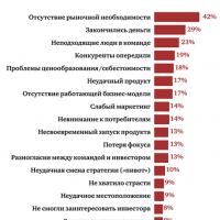 Five best business ideas that brought millions What business to open so as not to go bankrupt